
Method for implementing dual-frequency output laser

A technology of lasers and microchip lasers, which is applied in the field of lasers and can solve problems such as large volume and limited impact resistance

Active Publication Date: 2009-01-28
FUZHOU PHOTOP QPTICS CO LTD
View PDF0 Cites 10 Cited by
  • Summary
  • Abstract
  • Description
  • Claims
  • Application Information

AI Technical Summary

Problems solved by technology

[0003] Since the He-Ne laser is a gas laser, it has a large volume and can be used in the laboratory environment, especially the impact resistance is limited, which also limits the application in some small size and volume measurements.

Method used


Image

  • Method for implementing dual-frequency output laser
  • Method for implementing dual-frequency output laser
  • Method for implementing dual-frequency output laser

Examples


Embodiment 1

[0023] Embodiment 1: Using optics to process the substrate of the first microchip laser and the substrate of the second microchip laser that meet the required thickness difference. The first microchip laser and the second microchip laser are fabricated from the first substrate and the second substrate with different thicknesses.

Embodiment 2

[0024] Embodiment two: Utilize optical processing to have the substrate of the first microchip laser of considerable thickness and the substrate of the second microchip laser, the substrate of the first microchip laser and the substrate of the second microchip laser are coated with different thickness photoresist films , the film thickness meets the requirement of thickness difference.

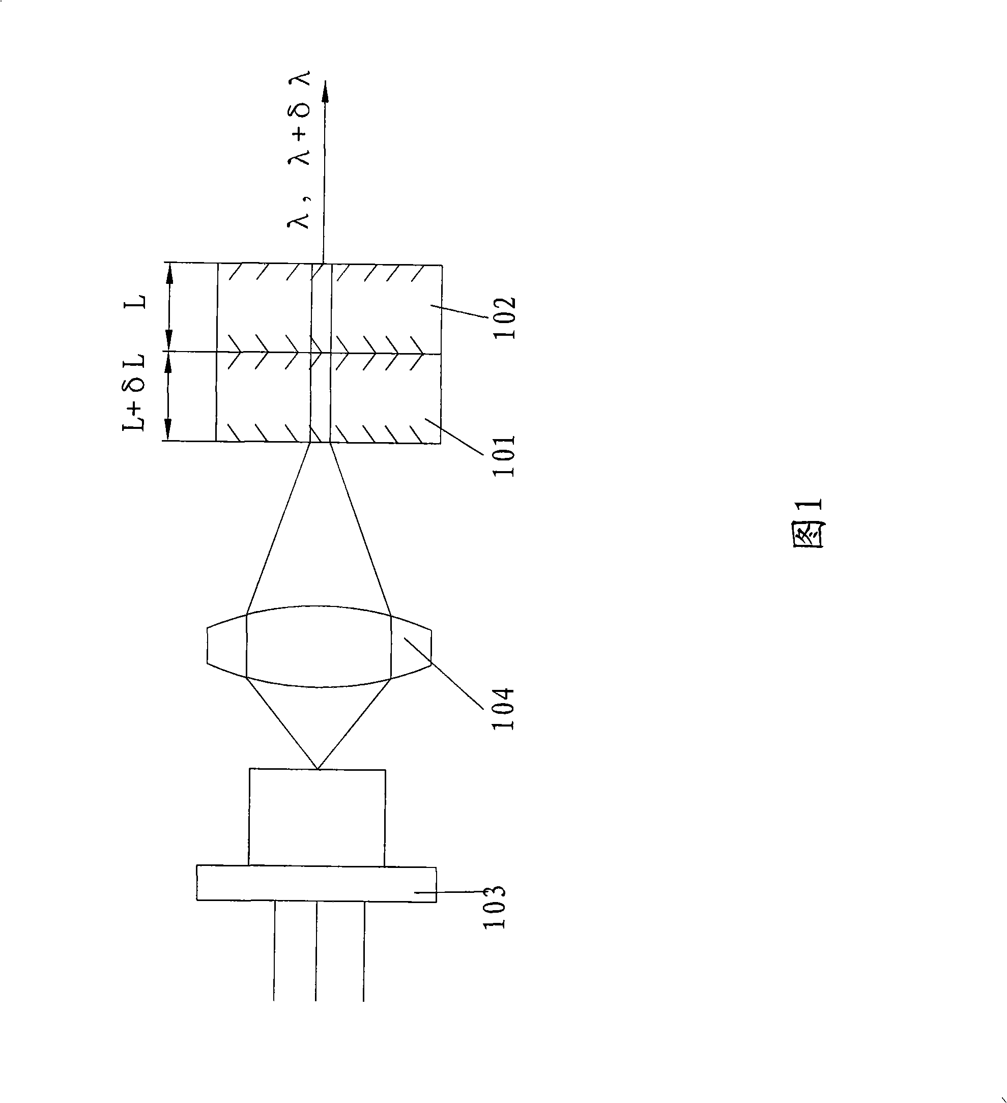
[0025] As shown in Figure 1, 101 and 102 are respectively independent microchip single longitudinal mode lasers, the thickness of the second microchip laser 102 is L, the thickness of the first microchip laser 101 is L+δL, and 103 is the pump of the semiconductor pump laser Pu light source, 104 is an optical coupling system.

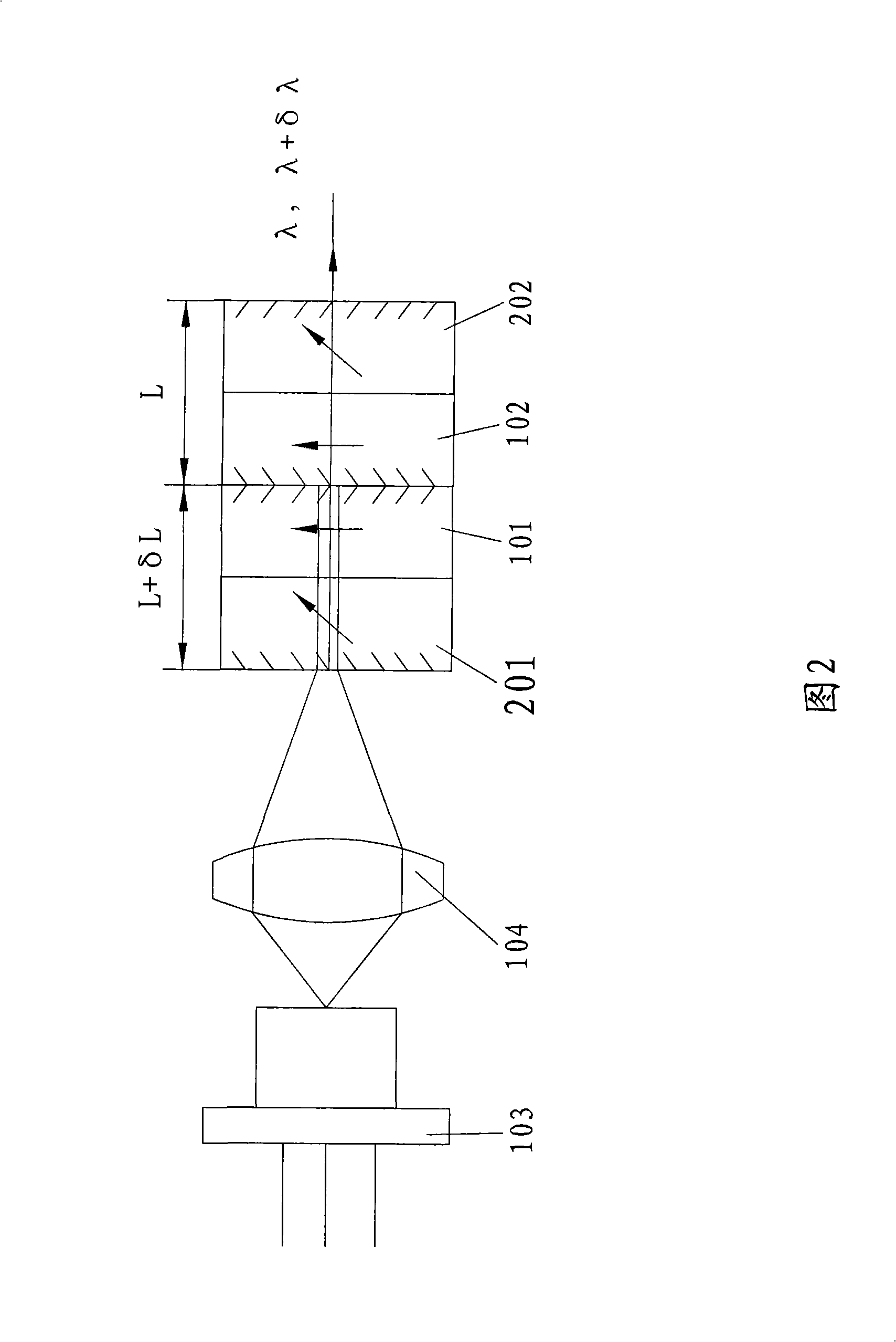
[0026] In Fig. 2, two groups of microchips are composed of laser gain medium and frequency doubling crystal to form an intracavity frequency doubling light output laser. 101 and 102 are laser gain media, and 201 and 202 are frequency doubling crystals.

Embodiment 3

[0027] Embodiment 3: The substrate of the first microchip laser and the second microchip laser substrate of the same tiny wedge angle are optically processed, and the substrate of the first microchip laser is symmetrical to the upside-down second microchip laser substrate place. Such as Figure 4 Among them, 501 and 502 are divided into microchip lasers with a wedge angle of δθ. δθ is so small that the microchip produces laser parallel to the allowable deviation range. L1 and L2 are the thicknesses of the pump light entering 301 and 302 from point C. Obviously, the pump point C is at L1-L2 will change when moving between A and B. This can be changed between the two frequencies by moving the pump point.


PUM


Abstract

The invention relates to the laser field, in particular to a method for realizing double-frequency output lasers. The method for realizing double-frequency output lasers comprises the following steps that: a first microchip laser and a second microchip laser are pumped by a pump light source, so as to ensure that the first microchip laser and the second microchip laser have optical thickness difference in cavity length, and furthermore, the range of the optical thickness difference is between 0 and 0.1 mm. The first microchip laser and the second microchip laser are a single whole through optical cement, gluing or deepened optical cement. Two single-longitudinal-mode output fundamental wave or frequency doubled laser output lasers with little difference in wavelength are formed through the pumping of the same pumping source, so as to obtain a microchip-type double-frequency laser which is used for double-frequency laser heterodyne interferometers and replaces the common double-frequency He-Ne laser. As the invention puts forward a novel method for realizing double-frequency output lasers, the double-frequency laser in small size can be obtained.

Description

technical field [0001] The invention relates to the field of lasers, in particular to a method for realizing a dual-frequency output laser. Background technique [0002] In the dual-frequency laser heterodyne interferometer, a dual-frequency output He-Ne laser is used. The helium-neon laser with dual-frequency output adds a magnetic field of about 0.03T to the axial direction of the helium-neon laser light tube. Due to the Zeeman effect and laser frequency pulling effect, the emitted light of the laser will contain two frequency components. They are left-handed circularly polarized light and right-handed circularly polarized light respectively. If υ1 and υ2 are used to represent their frequencies, the frequency difference δυ=υ1-υ2 is about 1.5MHZ. The frequency difference δυ is proportional to the strength of the external magnetic field. If the external magnetic field remains unchanged, the frequency difference will not change. [0003] Since the He-Ne laser is a gas laser...

Claims


Application Information

Patent Timeline
IPC IPC(8): H01S3/10H01S3/102H01S3/107
Inventor 吴砺凌吉武卢秀爱马英俊胡企铨
Owner FUZHOU PHOTOP QPTICS CO LTD
Learn More