Key assembly for vehicle ignition locks

a technology for ignition locks and keys, applied in the field of automotive security systems, can solve problems such as affecting the operation of rfid security systems, failure of transponders, and weakening the strength of signals sent to receivers, so as to reduce the potential for damage, prevent the application of impact forces, and reduce the effect of impact force applied

Inactive Publication Date: 2005-09-27
STRATTEC SECURITY
View PDF102 Cites 22 Cited by
  • Summary
  • Abstract
  • Description
  • Claims
  • Application Information

AI Technical Summary

Benefits of technology

[0017]Further in accordance with the invention, the injection molding process is conducted so as to minimize impact forces applied to the transponder during the molding process. Preferably, the undermold material is injected, in liquid form, through a gate that directs the material against a corner of the transponder causing the material to be split into two portions. Consequently, the liquid material that forms the undermold encircles the transponder as the material is being injected producing substantially even hydrostatic pressures. Encircling the transponder with the liquid material (which will eventually harden to form the undermold of the key assembly), substantially prevents the application of impact forces directly to the planar surfaces of the transponder, with an attendant reduction in the potential for damage to the transponder which could cause the device to fail.
[0018]In accordance with a feature of the invention, during the injection molding process, strategically located voids are formed in the undermold. These voids, which can be extremely small, eliminate pressure differentials which can otherwise develop between the adjacent portions of the mold. Eliminating the potential for a pressure differential prevents the transponder from shifting or cracking within the key assembly during overmolding.
[0019]Another benefit of molding the key assembly in two stages, namely first undermolding and subsequently overmolding, is that while the plastic is cooling following the injection molding process, overall heat and compressive force imposed on the transponder are substantially reduced. While the harder plastic material undergoes a greater degree of compression during cooling, the impact on the transponder is minimized because less material is used in forming the undermold.
[0020]Moreover, the component tending to cause a shift in the resonance of transponders for key assemblies used in RFID systems is substantially eliminated using the overmolding process provided by the invention. The softer plastic material which is used to form the overmold portion of the key head tends to abate thermal problems because the overmold material is less inclined to exert pressure and distort the transponder to the degree that harder material would. However, softer material is more prone to mechanical deformation by shear or torsional forces.
[0021]A further benefit of the present invention is the use of an injection molding device which supports and contains the transponder within the key assembly along its weakest axis to prevent cracking, fracturing, and other adverse effects, any of which can contribute to failure. The mold plates forming the molds that are used in molding the undermold and the overmold of the key assembly further serve to reduce, even prevent thermal excursion during manufacture of the key assembly because the mold plates function as heat sinks. The mold plates absorb auxiliary heat and thermal energy so that the affects of the heat upon the transponder in both the undermold and overmold processes are substantially reduced. Preferably, the mold plates comprise a relatively massive material with good heat transfer characteristics.
[0022]The improved process for manufacturing RFID systems incorporating known transponders, such as those produced by Texas Instruments, Inc. and Motorola, minimizes the impact and compressive force applied along the weak axis (or axes in the case of the Motorola device) of the transponder and, thus, reduces the chance that the transponder will fail.

Problems solved by technology

The inventors have found a problem involving a shift in inductance of the coil and the capacitance of the capacitor of the resonant circuit of the transponder which affects the operation of RFID security systems which occurs when the transponders are used in conjunction with prior key assembly designs.
A shift in the inductance and capacitance of the transponder's resonant circuit changes the resonant frequency of the transponder which can result in failure of the transponder to receive the interrogation signal being transmitted, or in the weakening of the strength of the signal sent to the receiver so that the receiver cannot detect signals transmitted by the transponder.
The end result is that the vehicle engine cannot be started and / or run using the ignition or otherwise.
However, the nature of harder plastic material is such that it tends to cause higher forces to be applied to the transponder under temperature excursions.
However, the softer material is more prone to mechanical deformation by externally applied forces.
This softer material can also adversely impact the structural integrity of the key head.

Method used


Image

  • Key assembly for vehicle ignition locks
  • Key assembly for vehicle ignition locks
  • Key assembly for vehicle ignition locks

Examples


first embodiment

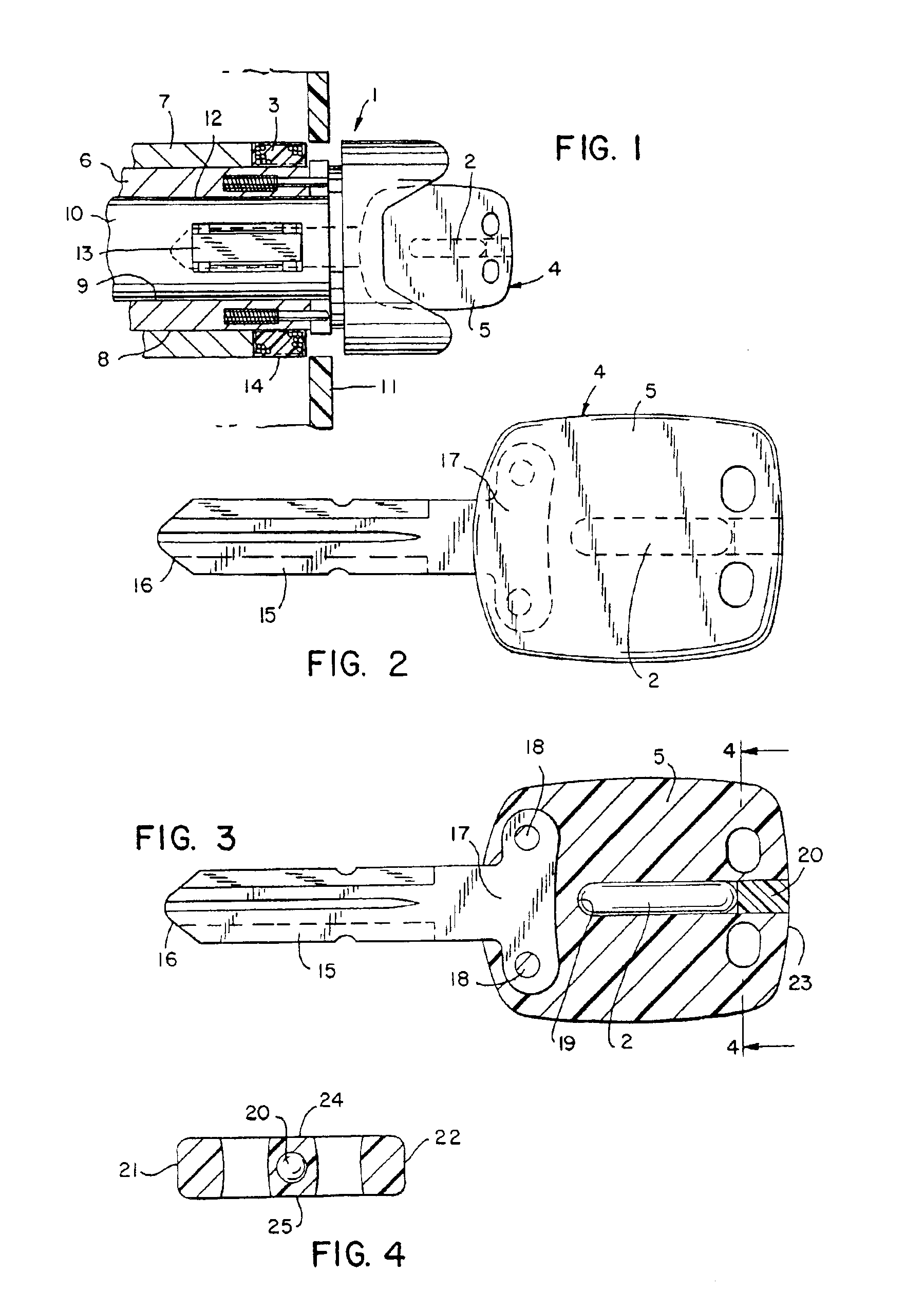
[0121]Referring now to FIGS. 2-4, there is illustrated a first embodiment for mounting the transponder 2 in the key head 5 of the key assembly 4. As shown, the key assembly 4 includes an elongated shank 15 having a toe end 16 and a heel end 17. The key head 5 preferably is integrally coupled to the heel end 17 of the shank 15 with pins 18 formed while the key head 5 is molded. As best shown in FIG. 3, the transponder 2 is mounted in a bore 19 formed in the key head 5. The bore is dimensioned to receive the transponder and a plug 20 is adapted to close off the bore 19. The bore 19 includes a blind end adapted to engage the transponder and an open end which opens to one end of the key head 5. As best shown in FIG. 3, the blind end of the bore 19 is spaced from the heel end 17 of the shank 15 and the longitudinal axis of the bore 19 is preferably aligned with the elongated shank 15. As shown, the bore 19 opens to the rear end of the key head 5. Alternatively, the open end of the bore 1...

second embodiment

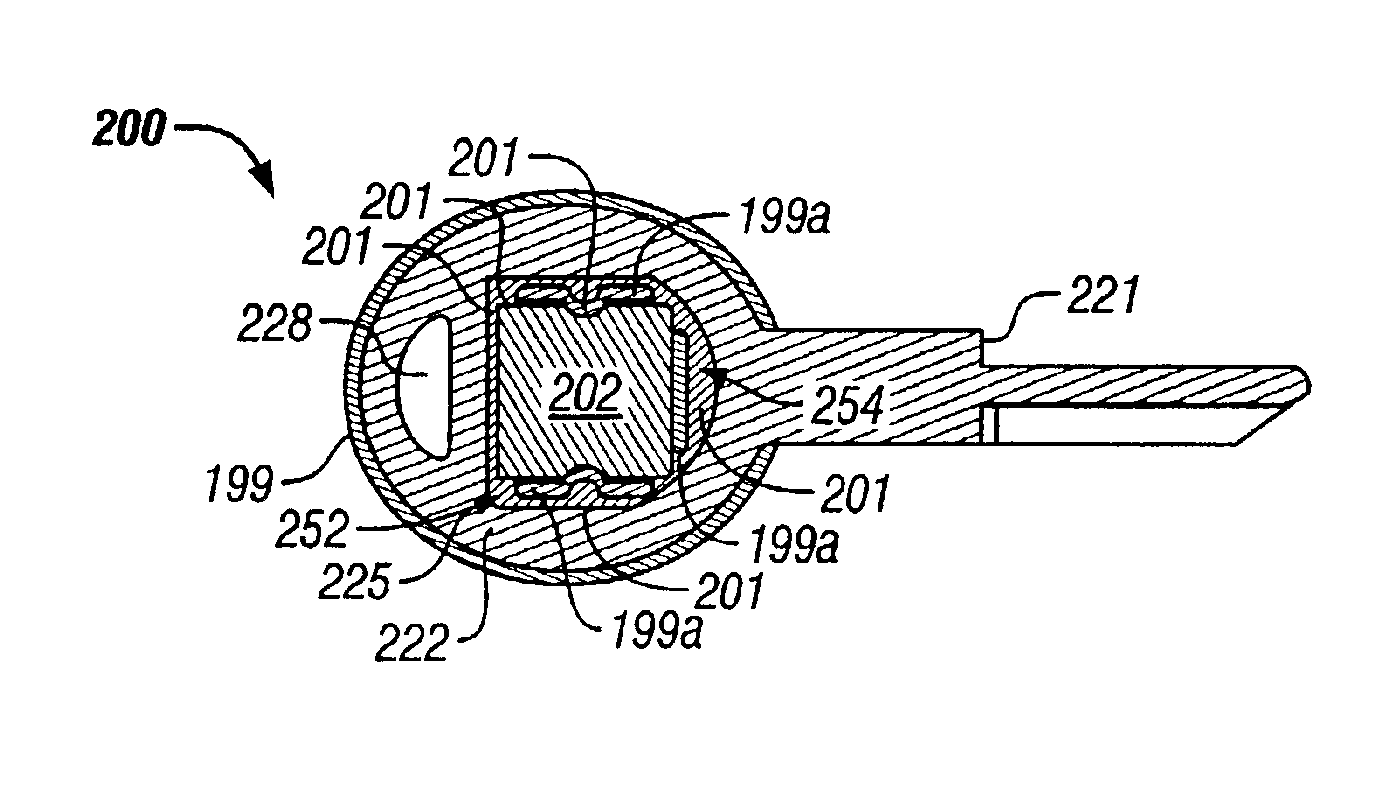
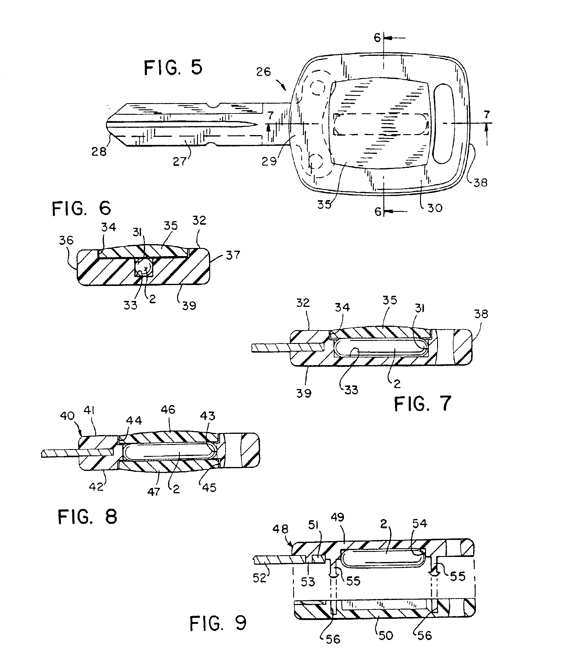
[0122]FIGS. 5-7 illustrate the key assembly of the present invention wherein the key assembly 26 includes the shank 27 having the toe end 28 and the heel end 29, and the key head 30 constructed of a plastic material integrally molded on the heel end 29 in the same manner as illustrated and described in FIG. 3. In this alternative embodiment, however, the transponder 2 is mounted within an opening comprising a substantially T-shaped recess 31 formed in one side 32 of the key head 30. The recess 31 is dimensioned to substantially correspond with the dimensions of the transponder 2. Additionally, a cushioning material, such as a silicone compound, may be supplied in the recess 31 at the time the transponder is installed. The recess 31 preferably has a closed bottom end 33 and an open top end 34 which opens to the side 32 of the key head 30. FIG. 6 illustrates the plug 35 which is preferably an adhesive-backed panel member which covers the transponder 2 and is received within the open t...

third embodiment

[0123]Yet the present invention is illustrated in FIG. 8. The key assembly of FIG. 8 is substantially similar to the key assembly of FIGS. 5-7, however, the opening which receives the transponder 2 extends completely through the key head 40 from one side 41 to the opposite side 42. As best shown in FIG. 8, the opening formed in the key head 40 includes a central section 43 for receiving the transponder 2 and a pair of opposite outer sections 44, 45 opening to opposite sides 41, 42, respectively, of the key head 40. A cushioning material such as a silicone compound may also be supplied in the central section 43 when the transponder 2 is installed. In this embodiment, the plugs 46, 47 for the openings extending through the key head 40 comprises a pair of adhesive-backed plugs 46, 47 received by the outer sections 44, 45 for covering the openings in the key head 40 such that the transponder 2 is positioned between the plugs 46, 47. The plugs 46, 47 of preferred embodiments of the prese...


PUM


Abstract

A method of decreasing resonant frequency shifting of an electrical circuit mounted on a vehicle key includes providing a frame in an opening in the head portion of a vehicle key and locating the transponder in the frame. The frame comprises substantially rigid non-metallic material, and the frame includes a support structure for supporting the transponder while decreasing forces produced on the transponder by thermal expansion and contraction of the head portion of the key, thereby decreasing shift in the resonance of the electrical circuit of the transponder. The frame, the transponder and the head portion of the key are overmolded providing an outer covering that encloses and protects the transponder.

Description

RELATED APPLICATIONS[0001]This application is a divisional of U.S. patent application Ser. No. 09 / 014,311 filed on Jan. 27, 1998 now U.S. Pat. No. 6,427,504, which is a continuation-in-part of U.S. patent application Ser. No. 08 / 503,429, filed Jul. 17, 1995 and issued on Mar. 14, 2000 as U.S. Pat. No. 6,035,677, which is a continuation-in-part of U.S. patent application Ser. No. 08 / 112,094, filed Aug. 26, 1993 and issued on Jul. 18, 1995 as U.S. Pat. No. 5,433,096.BACKGROUND OF THE INVENTION[0002]The present invention relates to an automobile security system, and more particularly, to a key assembly for use in a vehicle ignition and lock unit.[0003]Various types of security systems used in conjunction with the ignition circuit of a vehicle are known in the art. Many of these systems include anti-theft and / or anti-tampering mechanisms which are incorporated to deter the unauthorized use of vehicles. An electronic vehicle ignition lock is a component of some of these systems which can...

Claims


Application Information

Patent Timeline
Patent Type & Authority Patents(United States)
IPC IPC(8): E05B19/04E05B19/00G07C9/00G06K19/04
CPCE05B19/04G06K19/04G06K19/048G07C9/00944Y10T70/7079Y10T70/7802Y10T70/7904Y10T70/7876
Inventor JANSSEN, DAVID C
Owner STRATTEC SECURITY
Why Eureka
Try Eureka