In particular, with regard to diesel engines, the main problems consist in the presence, within the exhaust gases, of
nitrogen oxides (
NOx) and particulate, while carbon oxides (CO) and hydrocarbons (HC) do not
pose a particular problem.
The particulate therefore cannot be accumulated indefinitely since large accumulations cause:a deterioration in performance, drivability and consumption of the engine, until, in the most extreme case, stalling of the engine occurs; anddestruction of the said particulate filter in the case of self-ignition and uncontrolled combustion of the particulate; in fact, the presence of large quantities of particulate, in particular driving conditions, may trigger “critical” regeneration phenomena consisting in the sudden and uncontrolled combustion of particulate: consequently, the high temperatures generated inside the
ceramic lattice of the particulate filter may result in damage to the filter itself.
The regeneration of a particulate filter forms the main problem associated with the use of this type of filter in the motor car industry.
In particular, the methods of automatically triggering combustion of the particulate based on the use of an additive require:an exhaust
system comprising a catalyst and a particulate filter which are incorporated inside a single housing (canister);a particulate filter with a very large volume, typically equivalent to about twice the cubic capacity of the engine;a gas fuel additive (based on
cerium) which allows a reduction in the temperature for automatic triggering of regeneration by about 100–150° C.;a very
complex system for adding and automatically metering the additive on-board the vehicle; andengine control methods for increasing the temperature at the inlet of the particulate filter, since the necessary temperature levels cannot in any case be reached in conditions of normal use of the engine; in fact, this type of system functions correctly only in the case of operation of the engine under medium loads, while in the case of prolonged operation under low loads (for example when driving in towns) and / or in the presence of low external temperatures (in winter), the temperature of the exhaust gases in many cases does not manage to reach the self-triggering temperature.
The methods of automatically triggering combustion of the particulate based on the use of an additive, although they allow automatic triggering of regeneration of the particulate filter in the region of 450–500° C. and the particulate filter produces a low backpressure, have the following major limitations which prevent adequate and complete exploitation of all their positive aspects:complexity, in particular of the system for adding and automatically metering the additive;need for installation of a large-volume particulate filter since the additive present in the
diesel fuel leaves a deposit of ash inside the particulate filter which gradually increases;need to “clean” in any case the particulate filter of the ash about every 80,000 km, despite the large volume of the particulate filter;
cerium, in fact, produces a large quantity of ash which accumulates inside the filter together with the particulate and cannot be eliminated by means of regeneration; this therefore results in a
gradual increase in the backpressure of the filter on the engine with the increase in distance travelled by the vehicle and the consequent need to perform periodically disassembly and cleaning of the filter in order to eliminate the ash which has accumulated; andhigh cost, both in the case of the system for adding and automatically metering the additive and in the case of the large-volume particulate filter.
In detail, the method based on
delay of the main injection has drawbacks due to the fact that the main injection may not be retarded beyond a certain limit, otherwise it would cause an unstable combustion which would result in misfiring, with the consequent production of white / blue
smoke and problems associated with driving performance, in particular lack of response.
For these reasons, with this method it is not possible to obtain, at low speeds and with low engine loads, high temperatures at the particulate filter inlet.
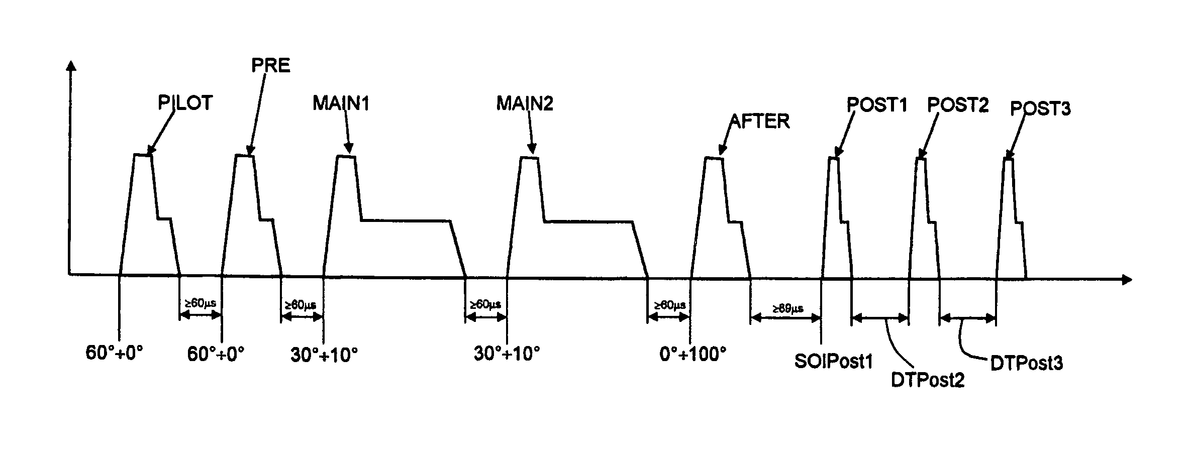
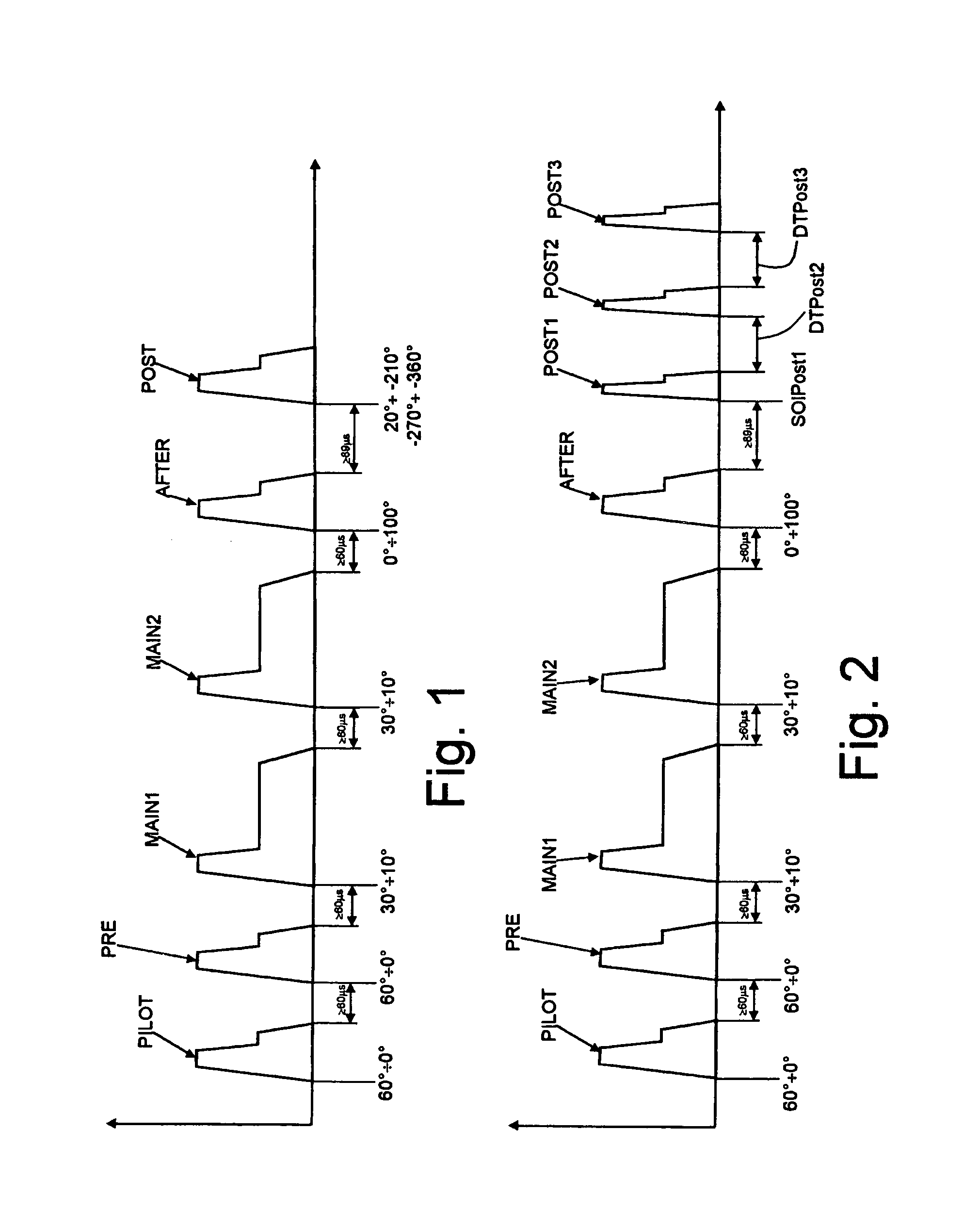
The presence of a post-injection POST performed with a large
delay with respect to the combustion TDC (100°–180° after the TDC) is indispensable for correct operation of the method for particulate filter regeneration proposed in the abovementioned
patent application EP-A-1,281,852, but has drawbacks associated with the problem of
dilution of the lubricating oil.
In fact, the considerable distance from the combustion TDC in terms of
crank angle, which is a characteristic of this type of injection, has the effect that the charging conditions inside the cylinder (in particular the pressure and temperature values) are unfavourable from the point of view of penetration of the jet of injected fuel.
Essentially, in these conditions, the aerodynamic resistance of the charge and the heat exchanges between the latter and the
liquid jet are not sufficient to prevent part of the fuel injected with the injection POST from striking the film of lubricating oil present on the cylinder liners.
The problems described above are aggravated by the fact that, in order to be able to inject during the injection POST the quantities of fuel necessary for reaching the temperature at which oxidation of the particulate is activated, it is required to operate with maximum penetration of the fuel jet where the jet strikes the cylinder walls; this inevitably results in interaction between the film of lubricating oil and the fuel.
From the literature on the subject it can be stated that even a reduction in the
viscosity in the region of 30% requires replacement of the lubricating oil, since the latter is no longer able to perform its main functions (reduction of friction, protection of mechanical parts against wear, heat disposal, etc.).
The problem of
dilution of the lubricating oil described above is present during the injection POST and therefore during regeneration of the particulate filter over the whole operating range of the engine; however, it becomes even more critical at engine points with low revolutions / loads.
In fact at these engine points, the conditions inside the cylinder are less favourable for the purposes of a reduction in penetration of the fuel jet, and the quantities of fuel injected during the injection POST necessary for reaching the temperature triggering oxidation of the particulate are higher.

