High-Q pulsed fragmentation in ion traps

a ion trap and high-q pulse technology, applied in mass spectrometers, separation processes, stability-of-path spectrometers, etc., can solve the problems of increasing the q value at the undesirable the q value decrease comes at the possible expense of decreasing the fragmentation efficiency, so as to improve the fragmentation efficiency and/or access, improve the rate at which ms/ms analyses may be performed, and reduce the lmco

Active Publication Date: 2005-09-27
THERMO FINNIGAN
View PDF28 Cites 69 Cited by
  • Summary
  • Abstract
  • Description
  • Claims
  • Application Information

AI Technical Summary

Benefits of technology

[0010]After a period of time following termination of the resonance excitation voltage pulse (referred to herein as the “high-Q delay period”), the RF trapping voltage applied to the ion trap is reduced to lower the Q to a second value (typically around 0.1), which in turn lowers the LMCO. The resonance excitation voltage pulse and high-Q delay periods are selected such that the RF trapping voltage is reduced sufficiently rapidly to prevent loss of low-mass fragments, thereby allowing their subsequent detection and measurement. Typical resonance excitation voltage pulse and high-Q delay periods are around 100 microseconds (μs) and 45–100 μs, respectively.
[0011]The high-Q pulsed technique described above offers several substantial advantages over the prior art resonance excitation technique, including the ability to perform fragmentation at high Q values (thereby improving fragmentation efficiencies and / or accessing higher-energy fragmentation processes) while maintaining the effective LMCO at a value sufficiently low to permit detection of fragment ions which would otherwise be unobservable. Further, the technique of the invention allows fragmentation to be completed in a significantly shorter time period relative to the prior art techniques, thus increasing the rate at which MS / MS analyses may be performed. Other advantages of the invention will be apparent to those of ordinary skill in the art upon review of the detailed description and associated figures.

Problems solved by technology

While the value of Q can be reduced to decrease the LMCO and allow detection of lower-mass fragments (which may be desirable, for example, in applications involving identification of peptide or protein structures), the decrease in Q comes at the possible expense of decreased fragmentation efficiencies.
Similarly, the value of Q may be increased from the default value to produce more energetic collisions (which may be required, for example, to fragment large, singly-charged ions), but such an increase in the Q value will have the undesirable effect of raising the LMCO precluding the detection of lower-mass fragments.

Method used


Image

  • High-Q pulsed fragmentation in ion traps
  • High-Q pulsed fragmentation in ion traps
  • High-Q pulsed fragmentation in ion traps

Examples


Embodiment Construction

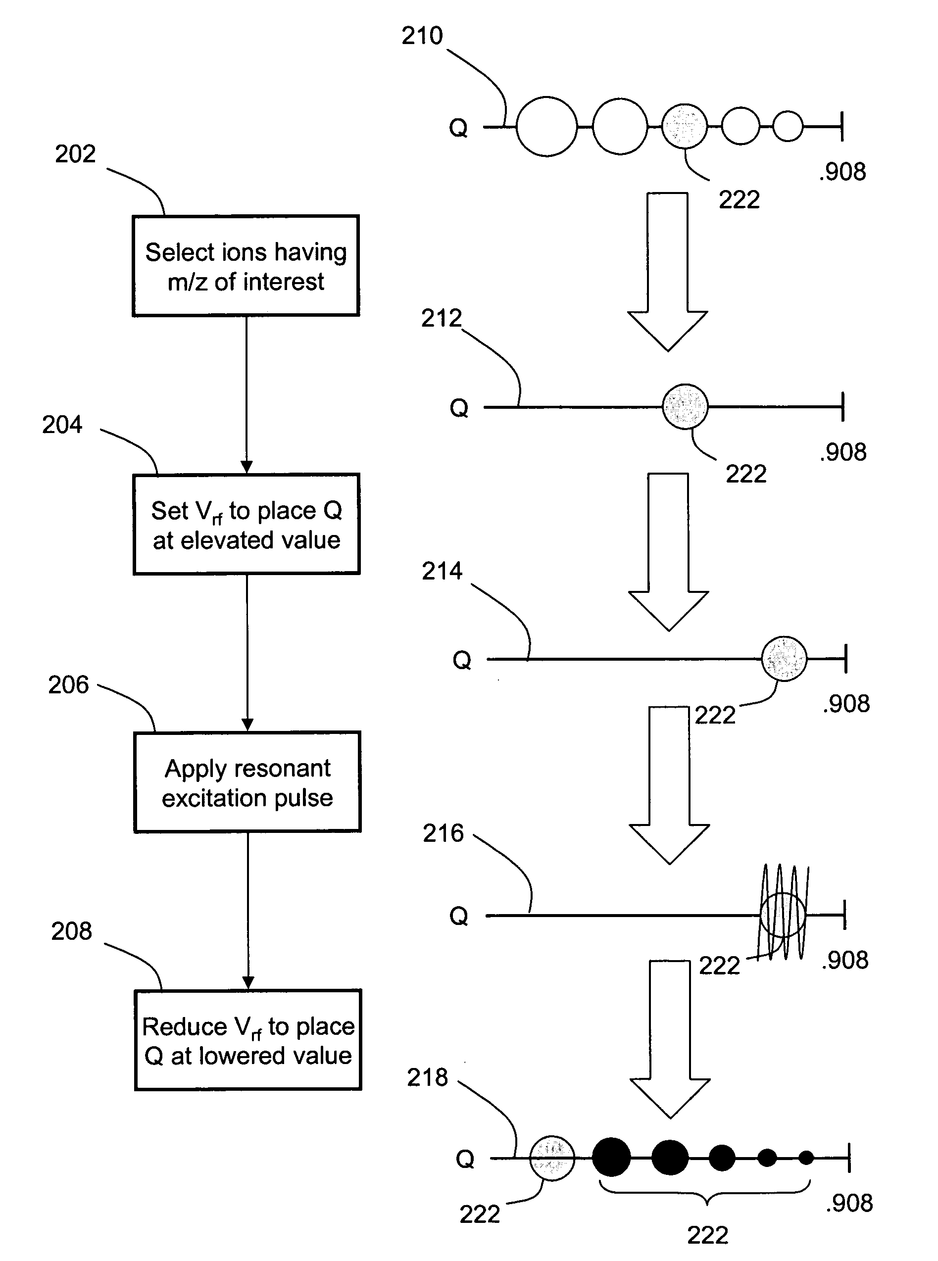
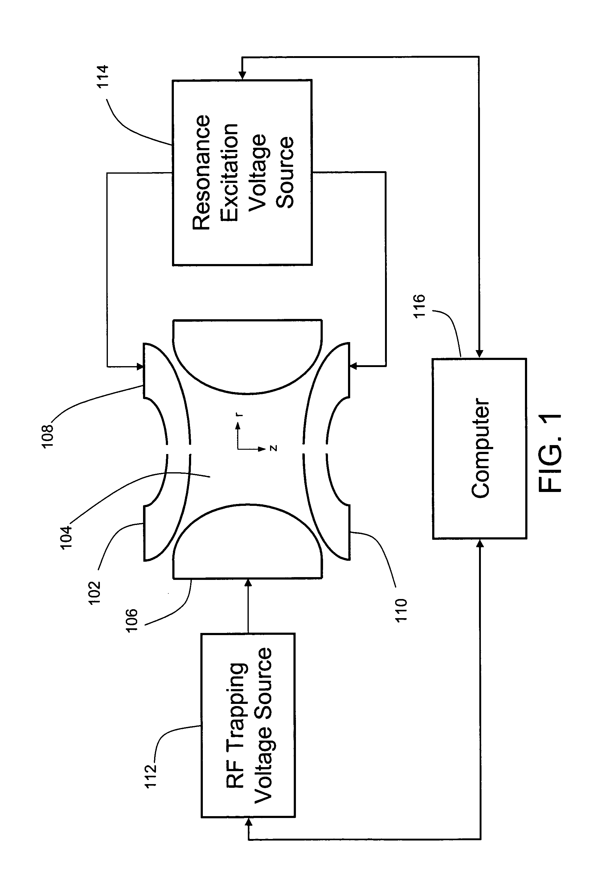
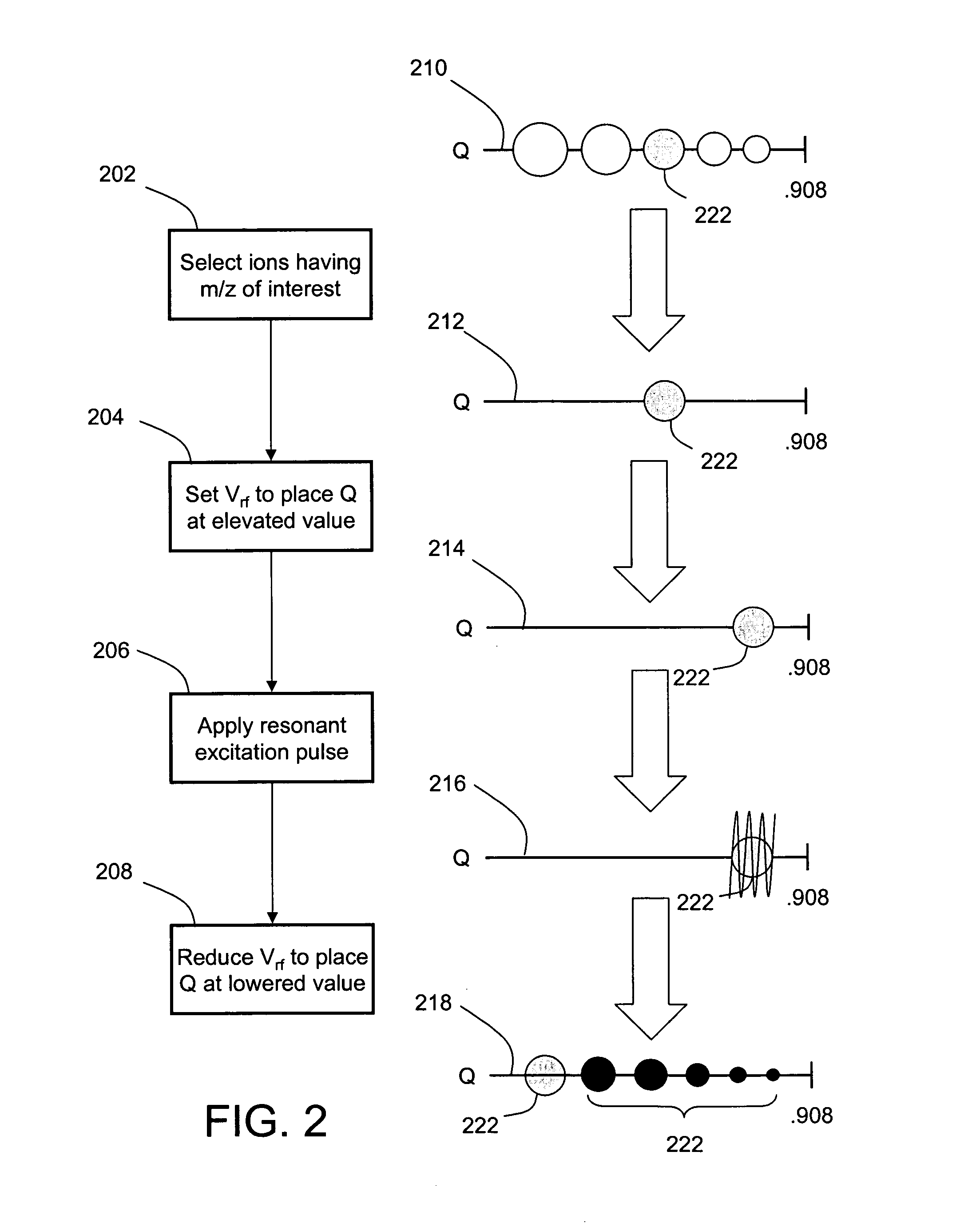
[0019]FIG. 1 is a simplified schematic of an exemplary ion trap 102 and associated components in which embodiments of the invention may be implemented. The design of ion traps for mass spectrometry applications is well known in the art and need not be discussed in detail herein. Generally, ion trap 102 includes a set of electrodes which bound a containment region 104 in which ions are trapped by generation of an RF trapping field. Those skilled in the art will recognize that certain ion trap geometries may also require a direct current (DC) component to be included in the trapping field. In FIG. 1, ion trap 102 is depicted in the form of a conventional three-dimensional (3-D) ion trap having a ring electrode 106 and entrance and end cap electrodes 108 and 110. Apertures formed in end cap electrodes 108 and 110 and aligned across the Z-axis permit injection and expulsion of ions into and from containment region 104. An RF trapping voltage source 112 coupled to ring electrode 106 (typ...


PUM


Abstract

Rapid and efficient fragmentation of ions in an ion trap for MS / MS analysis is achieved by a pulsed fragmentation technique. Ions of interest are placed at an elevated value of Q and subjected to a relatively high amplitude, short-duration resonance excitation pulse to cause the ions to undergo collision-induced fragmentation. The Q value of the ions of interest is then reduced before significant numbers of ion fragments are expelled from the ion trap, thereby decreasing the low-mass cutoff and allowing retention and subsequent measurement of lower-mass ion fragments.

Description

BACKGROUND OF THE INVENTION[0001]1. Field of the Invention[0002]The present invention relates generally to mass spectrometry, and more specifically to the use of ion traps for multistage (MS / MS) mass spectrometry.[0003]2. Description of the Related Art[0004]One of the strengths of ion traps is their ability to be used for multiple stages of mass analysis, which is commonly referred to as MS / MS or MSn. MS / MS typically involves fragmentation of an ion or ions of interest in order to obtain detailed information regarding the ion's structure. When performing MS / MS in an ion trap, there are various ways to activate ions in order to get them to fragment. The most efficient and widely used method involves a resonance excitation process. This method utilizes an auxiliary alternating current voltage (AC) to be applied to the ion trap in addition to the main trapping voltage. This auxiliary voltage typically has a relatively low amplitude (on the order of 1 Volt (V)) and a duration on the ord...

Claims


Application Information

Patent Timeline
Patent Type & Authority Patents(United States)
IPC IPC(8): H01J49/34H01J49/42
CPCH01J49/0063H01J49/42
Inventor SCHWARTZ, JAE C.
Owner THERMO FINNIGAN
Why Eureka
Try Eureka