
Rotary electric motor having concentric annular members

a technology of concentric annular members and electric motors, which is applied in the direction of magnetic circuit rotating parts, magnetic circuit shapes/forms/construction, electric devices, etc., can solve the problems of deterring the effect of torque ripple and flux interference between adjacent poles, delaying the output torque of pulsating, and affecting the effect of torque ripple and flux interference, so as to facilitate the removal and replacement of individual stator groups

Inactive Publication Date: 2005-09-27
MATRA MFG & SERVICES
View PDF14 Cites 25 Cited by
  • Summary
  • Abstract
  • Description
  • Claims
  • Application Information

AI Technical Summary

Benefits of technology

[0011]While the present invention has useful applicability in various motor drive applications, it is advantageously suitable for a vehicle drive in which the rotor is structured to surround the stator, the rotor being secured to a housing for direct attachment to a vehicle wheel. The annular rotor is thus at a substantial radial distance from the axis of rotation. The rotor housing is journalled for rotation about a stationary shaft at the axis of rotation through bearings. In an embodiment in which the rotor comprises permanent magnets, a large number of permanent magnets can be substantially evenly distributed along the annular ring. As a programmed microprocessor has the capability of generating extremely high rate of switching signals, a wide vehicle speed range is available without need for transmission gear shifting. The groups of separate electromagnets form a relatively thin annular stator ring that is spaced from the axis of rotation by a radial distance, which preferably is substantially greater than the radial dimension between inner and outer diameter boundaries of the stator ring, and secured to the shaft. The configuration of the present invention, wherein electromagnet pole pairs each form isolated magnetic structures formed in a thin annular ring, has been found to provide advantageous effects. With this arrangement, flux can be concentrated, with virtually no loss or deleterious transformer interference effects, at the radial air gap for optimum interaction with the permanent magnet rotor. As a result, extremely high torque is available with a high efficiency that significantly extends battery life.
[0012]As an additional advantage, each stator group is individually secured in the stator annular ring structure, wherein removal and replacement of an individual stator group is facilitated. Thus, if a particular stator winding group should become damaged, for example by a fault in the pole structure or winding, the individual stator group can be replaced without removing or replacing the entire stator unit. As a related advantage, with the use of a large number of single pole pair stator groups, the motor can continue to operate in a satisfactory manner even if one or more particular electromagnet pole group energization fails.
[0013]A further advantage of the present invention is that, to a large extent, stator and rotor pole face dimensions and spacings between poles are relatively independent of each other. A timed switched energization scheme can be programmed to be optimized for a particular structural configuration. A preferred embodiment, in which operation has been found to be particularly advantageous, implements the following structural features. An odd number of stator groups is utilized. The stator poles have pole faces at the air gap that are of substantially uniform angular extent. The permanent magnet rotor poles are of substantially equal angular dimensional extent at the air gap, which is different from the stator pole face dimension. The angular distance between the centers of the pole faces of each stator group is substantially uniform throughout the periphery of the stator and differs from the angular distance between the centers of the stator pole faces of adjacent groups. The angular distance between the centers of the pole faces of each stator group also is different from the angular distance between the centers of adjacent permanent magnet poles of the rotor. Gaps between adjacent stator pole faces within each group are substantially equal for all groups and different from gaps between adjacent stator groups. The rotor pole faces are separated substantially uniformly by gaps, the gaps between adjacent rotor pole faces being different from the gaps between adjacent stator pole face within a stator group.

Problems solved by technology

For example, simultaneous switching of all motor phase windings can cause pulsating output torque.
However, switching of adjacent windings at different times leads to detrimental effects if the windings are linked to a continuous magnetic circuit path, as the flux changes due to the changed energization of the winding of one pole effects the flux of an adjacent pole.
Heidelberg et al. provides modifications in which some poles of a group are not wound and / or the pole structure of all poles within a group are not of uniform configuration, thus deterring the effects of torque ripple and flux interference between adjacent poles.
Such modifications sacrifice torque characteristics.
The unwound poles do not contribute to torque and can negatively interact with rotor permanent magnets.
Such configurations complicate the manufacturing process and compromise motor efficiency.

Method used


Image

  • Rotary electric motor having concentric annular members
  • Rotary electric motor having concentric annular members
  • Rotary electric motor having concentric annular members

Examples


Embodiment Construction

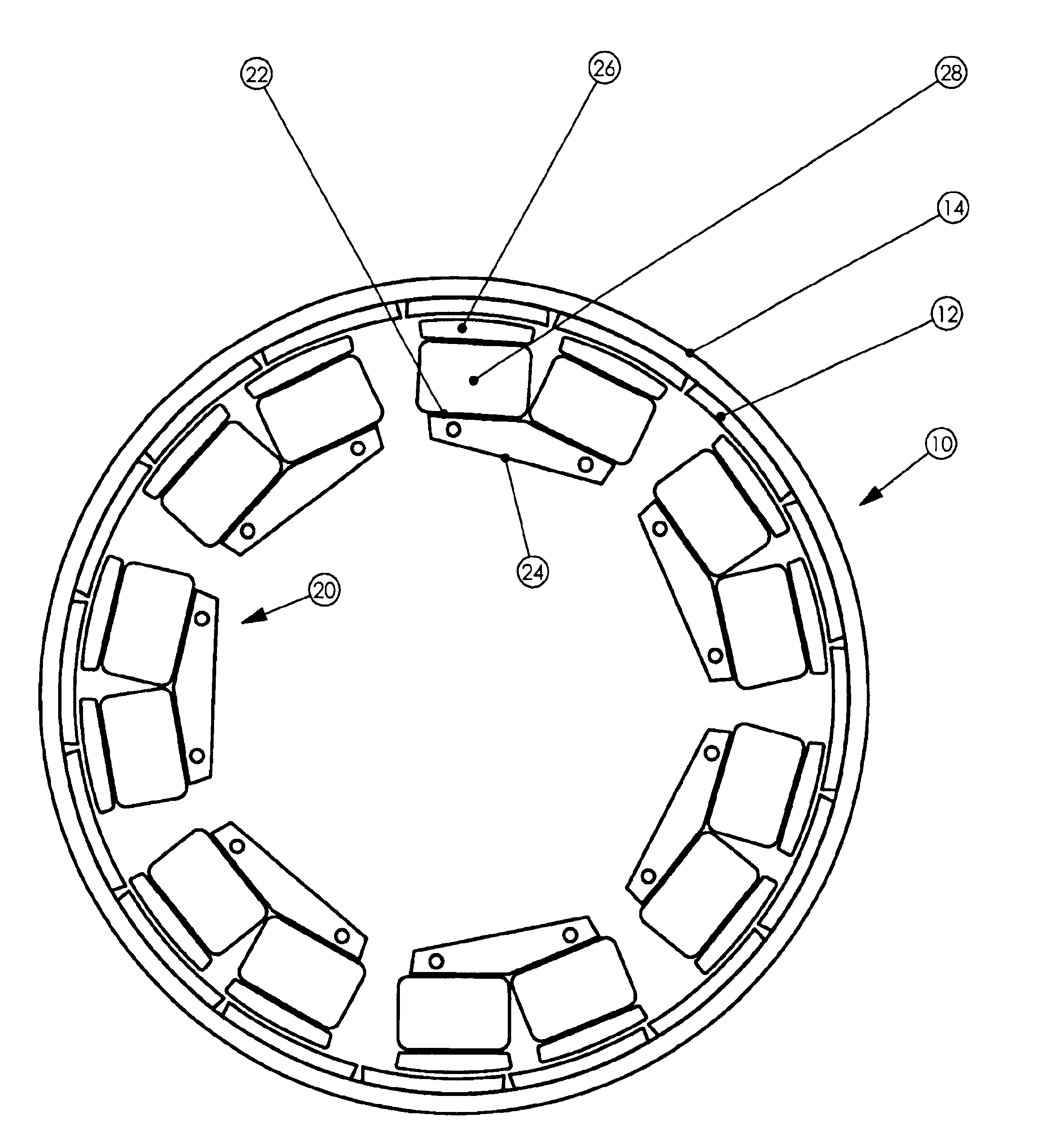
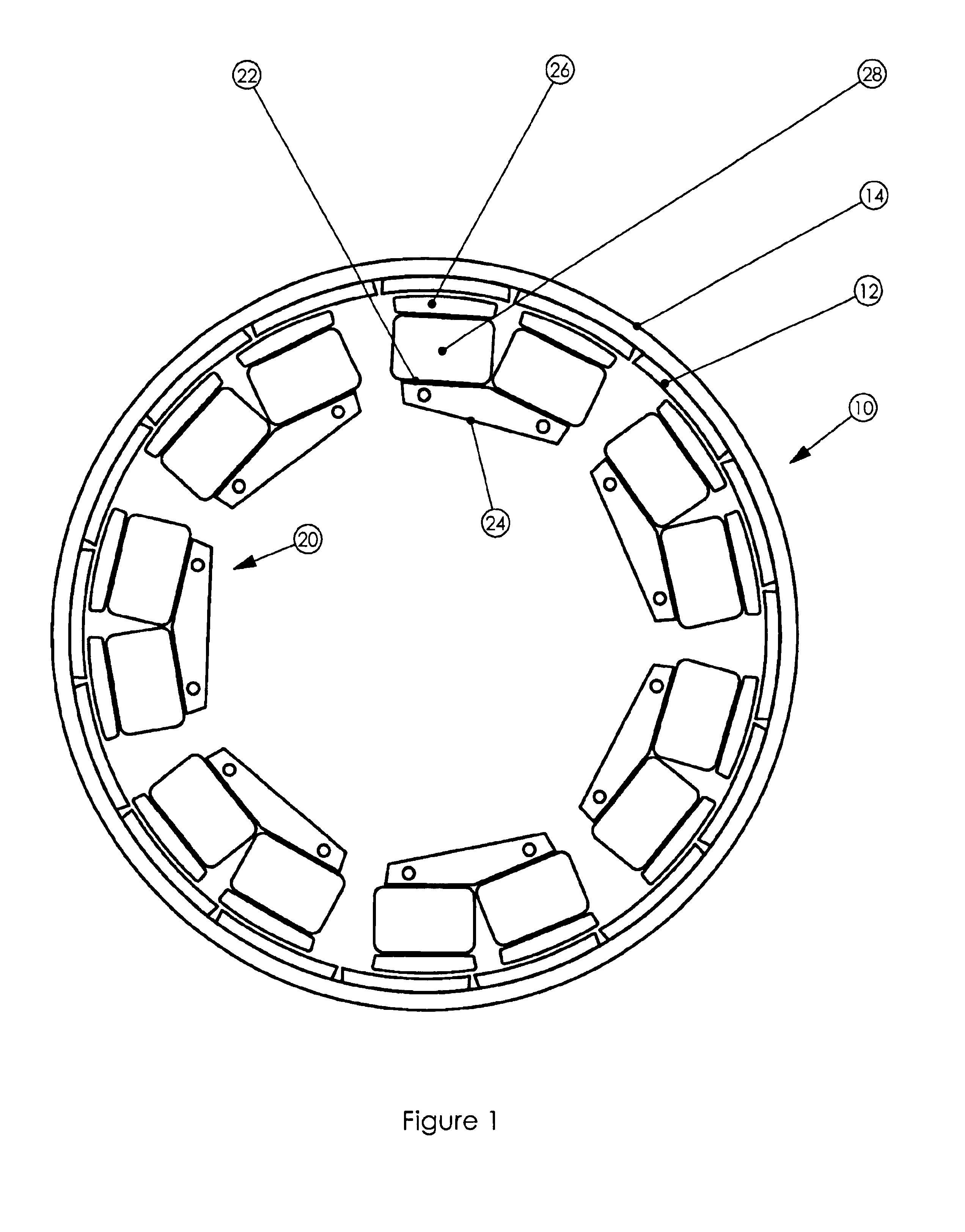
[0024]FIG. 1 is a plan diagram of a stator and rotor layout of a preferred embodiment of the motor of the present invention. Rotor member 10 is an annular ring structure having sixteen permanent magnets 12 substantially evenly distributed along cylindrical back plate 14. The permanent magnets are rotor poles that alternate in magnetic polarity along the inner periphery of the annular ring. The back plate comprises magnetically permeable material that serves as a magnetic return path between adjacent permanent magnetic poles 12. The rotor surrounds a stator member 20, the rotor and stator members being separated by a radial air gap. Stator 20 comprises seven elements or groups of pole pairs 22 of uniform construction that are evenly distributed along the air gap. Each stator group comprises a generally u-shaped magnetic structure 24 having two pole faces 26 at the air gap. Each stator group structure is separate, and magnetically isolated, from adjacent groups. The legs of the pole p...


PUM


Abstract

A rotary electric motor in which rotor and stator members are each configured as annular rings, concentric with respect to each other, about an axis of rotation. Either of the rotor or stator members is formed of groups of electromagnet poles, the groups substantially equidistantly distributed along the angular extent of the annular ring, each of the groups comprising magnetic material magnetically isolated and separated from the other groups. The other member comprises a plurality of permanent magnet poles substantially equidistantly distributed with alternating magnetic polarity along the angular extent of the radial air gap formed between the members, the permanent magnet poles having a common magnetic return path.

Description

RELATED APPLICATIONS[0001]The present application claims priority of U.S. Provisional Patent Application ser. No. 60 / 194,594, filed Apr. 5, 2000. This application contains subject matter related to applicants' copending U.S. application Ser. No. 09 / 571,174, filed May 16, 2000, and copending U.S. application Ser. No. 09 / 826,423, filed concurrently herewith.FIELD OF THE INVENTION[0002]The present invention relates to rotary direct current electric motors, more particularly to motors having first and second annular ring members concentrically arranged about an axis of rotation and separated from each other by a radial air gap, one of the members comprising separate magnetically isolated wound electromagnetic pole groups.BACKGROUND[0003]Direct current motors have versatility in a wide range of applications. The availability of a battery power source for dc motor equipped devices facilitates a portability aspect that is not readily available for a-c motor drives. Electronic controls, suc...

Claims


Application Information

Patent Timeline
IPC IPC(8): B62M23/02B62M7/12B62M7/00H02K1/18H02K21/22H02K29/06H02K1/27B62M6/40B62M6/65
CPCB62M6/40B62M7/12H02K1/187H02K21/22B60L3/0061B60L15/20H02K1/2786B60L2240/423B60L2220/44B60L2240/421H02K29/06Y02T10/72Y02T10/64H02K1/2791
Inventor MASLOV, BORISPYNTIKOV, ALEXANDER
Owner MATRA MFG & SERVICES
Learn More