

Method and system for monitoring plasma using optical emission spectroscopy
a technology of optical emission spectroscopy and plasma, applied in the direction of optical radiation measurement, semiconductor/solid-state device testing/measurement, instruments, etc., can solve the problems of insufficient dissociation of precursors, insufficient dissociation to actually perform the desired function, contamination of future deposition processes,
- Summary
- Abstract
- Description
- Claims
- Application Information
AI Technical Summary
Benefits of technology
Problems solved by technology
Method used
Image

Examples
Embodiment Construction
[0018]One or more specific embodiments of the present invention will be described below. In an effort to provide a concise description of these embodiments, not all features of an actual implementation are described in the specification. It should be appreciated that in the development of any such actual implementation, as in any engineering or design project, numerous implementation-specific decisions must be made to achieve the developers' specific goals, such as compliance with system-related and business-related constraints, which may vary from one implementation to another. Moreover, it should be appreciated that such a development effort might be complex and time consuming, but would nevertheless be a routine undertaking of design, fabrication, and manufacture for those of ordinary skill having the benefit of this disclosure.
[0019]Integrated circuitry, in one form or another, is present in substantially all consumer, commercial, and industrial electronic devices. For example, ...
PUM
| Property | Measurement | Unit |
|---|---|---|
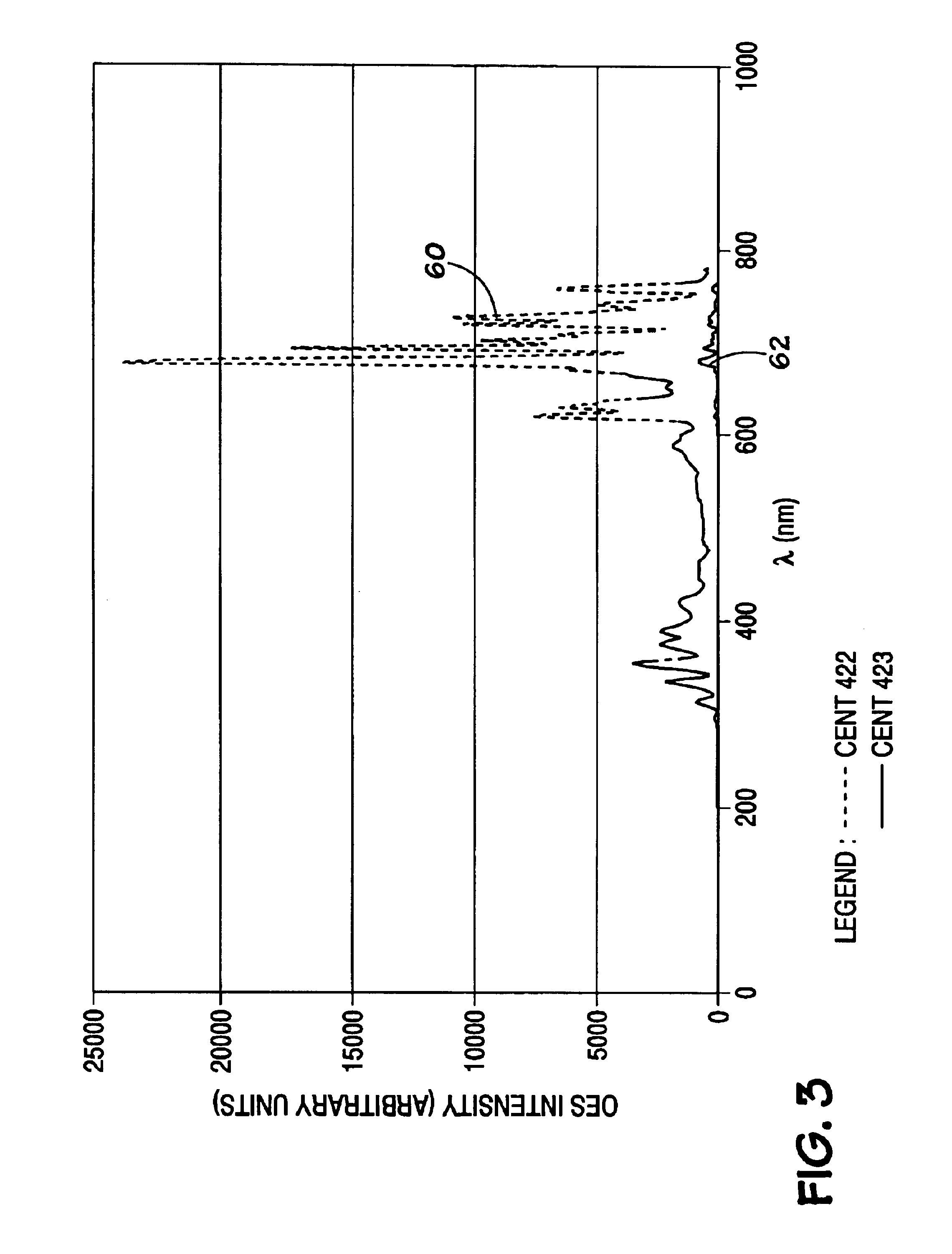
| spectra | aaaaa | aaaaa |
| AC voltage | aaaaa | aaaaa |
| RF voltage | aaaaa | aaaaa |
Abstract
Description
Claims
Application Information