
System for monitoring substrate conditions

a substrate and monitoring system technology, applied in the direction of dynamo-electric components, instruments, structural associations, etc., can solve the problems of reducing the transmission of ligh

Inactive Publication Date: 2005-09-27
ROCKWELL AUTOMATION TECH
View PDF5 Cites 77 Cited by
  • Summary
  • Abstract
  • Description
  • Claims
  • Application Information

AI Technical Summary

Benefits of technology

[0007]The present invention relates generally to systems and methods for monitoring a substrate. According to one aspect of the present invention at least one condition of a process associated with a substrate is monitored by utilizing an optical waveguide, at least part of which is integral with or embedded in the substrate. For example, the optical waveguide can be formed of a material that facilitates transmission of light through the waveguide and that has physical properties similar to the substrate itself. In this way, the waveguide can respond to process conditions and usage similarly as the substrate, such that variations in light transmitted in the waveguide and received at a measuring system can be employed to determine a condition or characteristic of the substrate and / or a process acting thereon.

Problems solved by technology

Articles can wear over time, such as due to frictional contact, chemical machining, or abrasion, for example.
Additionally, polishing and buffing pads can themselves wear during CMP processing.
For instance, polishing and buffing pads can become thinner due to mechanical loss of material as they polish and buff.
These pads have to be replaced when they become overly thin and worn.
MEMS devices can also experience surface wear and material loss during normal operation.
As a result, one or more areas of the MEMS device can experience surface wear.
Repeated exposure to such mechanical interaction can lead to device failure, inoperability or malfunction.

Method used


Image

  • System for monitoring substrate conditions
  • System for monitoring substrate conditions
  • System for monitoring substrate conditions

Examples


Embodiment Construction

[0047]The present invention will now be described with reference to the drawings, wherein like reference numerals are used to refer to like elements throughout.

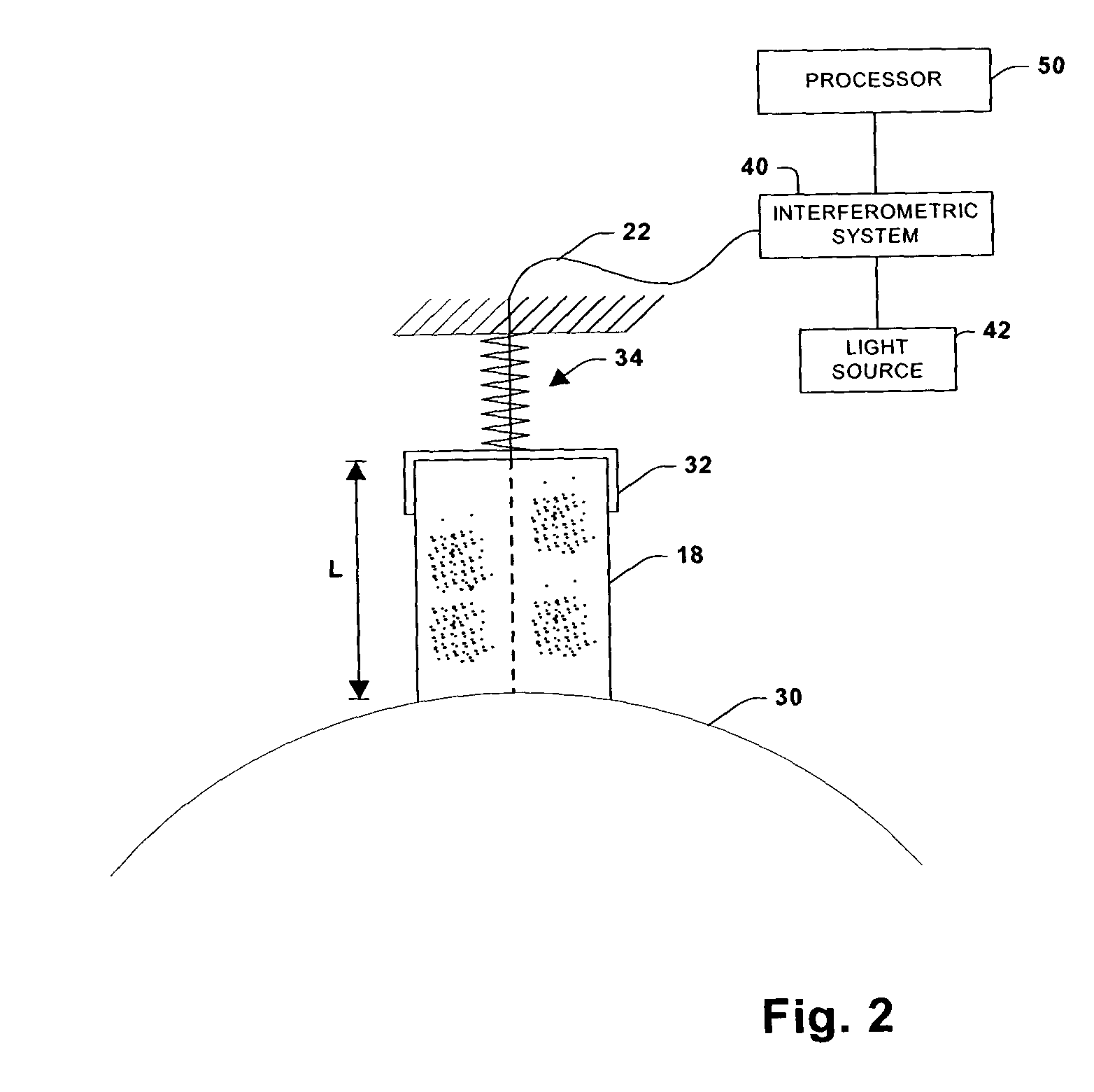
[0048]The present invention employs optical signals (e.g., via optical fiber(s) embedded in an article) to provide data relating to the article and / or data relating to environmental conditions the article is subjected to. Such data can include, for example, the amount of wear and the rate of wear of the article. Furthermore, the present invention can provide data relating to surface condition assessment, article temperature and / or environment temperature, motor speed, and article pressure and / or environmental pressure.

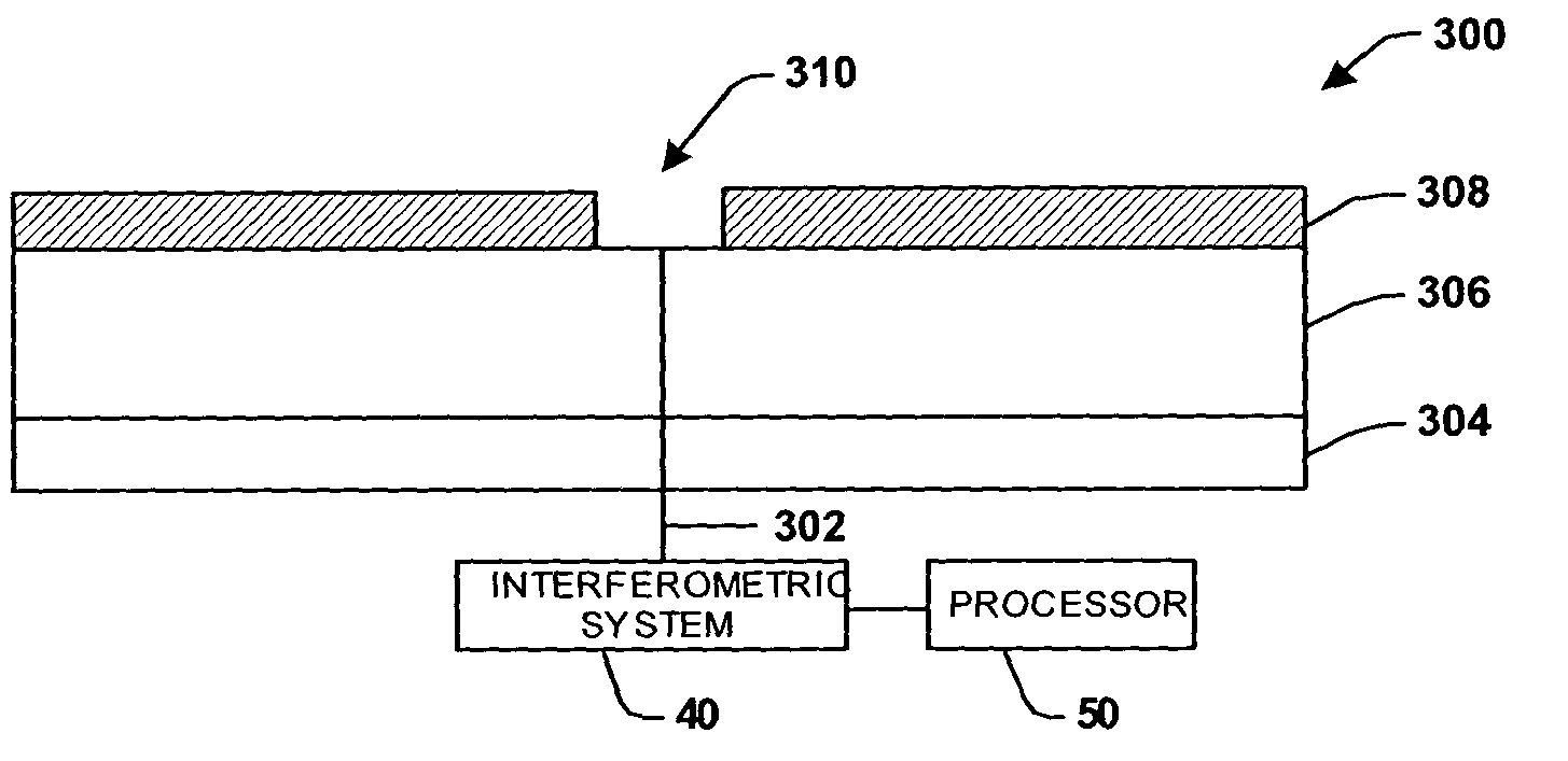
[0049]Referring initially to FIG. 1, an article 18, such as can include, for example, a substrate and / or a micro-electro-mechanical system (MEMS), is shown in perspective view with an optical fiber 22 embedded therein. The optical fiber 22 is embedded such that its length direction is substantially parallel to t...


PUM


Abstract

A system for determining at least one condition of a substrate includes an optical waveguide for transmitting light from a light source. The optical waveguide can be embedded in the substrate and operatively coupled to an interferometric system. The interferometric system is operatively coupled to a processor. The interferometric system provides the processor with information relating to transmissions through the wave guide, which are indicative of substrate conditions and / or operations being performed relative to the substrate.

Description

CROSS REFERENCE TO RELATED APPLICATIONS[0001]This application is a continuation-in-part application of U.S. patent application Ser. No. 09 / 625,094 filed Jul. 25, 2000 entitled SYSTEM FOR MONITORING BEARING WEAR, which is a continuation-in-part of U.S. patent application Ser. No. 09 / 504,440 filed Feb. 16, 2000 now U.S. Pat. No. 6,359,690, entitled APPARATUS, SYSTEM AND METHOD FOR DETERMINING WEAR OF AN ARTICLE, which is a continuation of U.S. patent application Ser. No. 09 / 253,785 filed Feb. 22, 1999 entitled SYSTEM FOR DETERMINING WEAR OF AN ARTICLE (which issued as U.S. Pat. No. 6,067,159), which is a continuation of U.S. patent application Ser. No. 08 / 959,610 filed Oct. 28, 1997 entitled APPARATUS, SYSTEM AND METHOD FOR DETERMINING WEAR OF AN ARTICLE (which issued as U.S. Pat. No. 6,111,643), all of which are hereby fully incorporated by reference.TECHNICAL FIELD[0002]The present invention generally relates to systems and methods for monitoring substrate conditions, and more parti...

Claims


Application Information

Patent Timeline
IPC IPC(8): G01B9/02G01B11/06
CPCG01B11/06H02K11/25H02K11/35H02K5/14
Inventor DISCENZO, FREDERICK M.
Owner ROCKWELL AUTOMATION TECH
Features
  • Generate Ideas
  • Intellectual Property
  • Life Sciences
  • Materials
  • Tech Scout
  • Unparalleled Data Quality
  • Higher Quality Content
  • 60% Fewer Hallucinations
Learn More