Earthquake resistant equipment rack

a technology for equipment racks and earthquakes, applied in the field of racks for electrical equipment, can solve the problems of high stress and deflection, add significantly to the labor and cost of manufacturing, and increase the overall weight and cost of racks, and achieve the effects of fewer components, increased overall strength, and reduced labor and cos

Inactive Publication Date: 2005-10-04
CK ACQUISITION HLDG INC
View PDF33 Cites 38 Cited by
  • Summary
  • Abstract
  • Description
  • Claims
  • Application Information

AI Technical Summary

Benefits of technology

[0009]It is a related object of the present invention to provide an electronic equipment rack having substantially increased overall strength without using heavier materials which otherwise would increase the racks overall weight and cost.
[0010]It is a further object to provide an electronic equipment rack having fewer components and requiring fewer manufacturing steps thereby keeping production costs to a minimum.
[0011]An additional object is to provide an electronic equipment rack with increased stiffness at different locations to accommodate required loads and stresses without increasing the desired dimensions and / or weight of the rack.
[0012]Generally, the present invention includes several embodiments of an equipment rack, a first comprising a base having unique characteristics to accommodate upstanding midrails at a central portion of the depth of the base. The midrails are in turn coupled to one another by a top frame member in a manner to provide desired structural integrity to particular standards relating to handling seismic energy. The midrail design presents possible problems in properly supporting equipment therein and handling cables or other connections to the supported equipment. In the present invention, the base is comprised of several components which allow proper structural characteristics to be achieved while accommodating cabling or other requirements through the central portion of the base. More particularly, the base may comprise a pair of outer base members which interlock with a base gusset member to form an integral base having a solid bottom with double wall thicknesses provided by the interlocking outer base and base gusset members. A base cover is then secured in position with the outer base and base gusset members in a manner to provide structural integrity from front to back and side to side in the base. The design of the base cover allows access through the base cover for cabling or other requirements. The base cover provides such advantages without interference into the equipment carrying space of the rack. In addition, the equipment rack of this embodiment may comprise a reinforced corner structure in association with the rails and top frame member. Each of the side rails of the equipment frame is formed as a generally U-shaped channel providing an amount of structural integrity. The top corners of the side rails are particularly susceptible to stresses due to seismic activity or vibration, and are preferably reinforced without the use of heavier gauge materials. In this embodiment, a gusset member is designed to mate into position within the U-shaped side rail member to effectively reinforce the corner area with a double wall thickness of material, but using similar gauge material throughout. Further, the gusset member is designed to be positively engaged with the top rail member in conjunction with the side rail members for added stiffening an strength. A tab provided on each end of the top rail member the side rail members as well as reinforcing gusset members for proper positioning and alignment of the components and to allow each to be secured to one another. The top rail member may also be configured to be constructed of top and bottom members of similar gauge material which fit in an interlinking manner to provide desired stiffness and strength characteristics. One of the top or bottom members also may be configured with ears that extend outwardly into adjacent relationship with the reinforcing gusset member at each corner, allowing further securing of the top rail therewith. In this manner, all vertical surfaces of the corner portions in the rack design are double wall thicknesses providing desired structural characteristics. The rack design of this embodiment further may be used in a modular manner, wherein two or more racks can be assembled with one another to provide different size and supporting requirements.
[0013]In another embodiment, an equipment rack is designed to combine characteristics of rack requirements as specified by regulatory agencies, such as ETSI and NEBS. In this embodiment, the base of the rack is comprised of several members which when assembled provide a plurality of structural box-like portions which provide desired structural characteristics and simplify manufacture and assembly. A base cover cooperates with other base members to provide a box in box type of design which enhances structural integrity using lighter gauge materials. Side rail members of the rack may be provided with embossed sections to enhance stiffness characteristics. Other unique attributes of the rack design will also become apparent. Also, similar to the first embodiment, the rack design of this embodiment further may be used in a modular manner, wherein two or more racks can be assembled with one another to provide different size and supporting requirements.
[0014]The embodiments of the invention improve strength and stiffness at maximum stress positions to increase the racks lateral force tolerance thereby increasing the racks strength in its weakest direction. The coupling positions of components which are subjected to the highest stress levels of any point on the equipment rack are designed to accommodate expected loads and stresses.

Problems solved by technology

Traditionally earthquake protection has been achieved by providing equipment racks or network bays with relatively massive bracing or using heavier materials, which both add significantly to the labor and cost in manufacturing.
In prior configurations, design of equipment racks have utilized different gauge materials to provide desired structural integrity, but results in added cost and problems in assembly.
If, however, the frame is more flexible, it will move at a rate different to that of the base and floor, and consequently experience high stresses and deflections.
Known equipment racks do not provide modularity or adaptable uses to accommodate differing equipment or environments.

Method used


Image

  • Earthquake resistant equipment rack
  • Earthquake resistant equipment rack
  • Earthquake resistant equipment rack

Examples


first embodiment

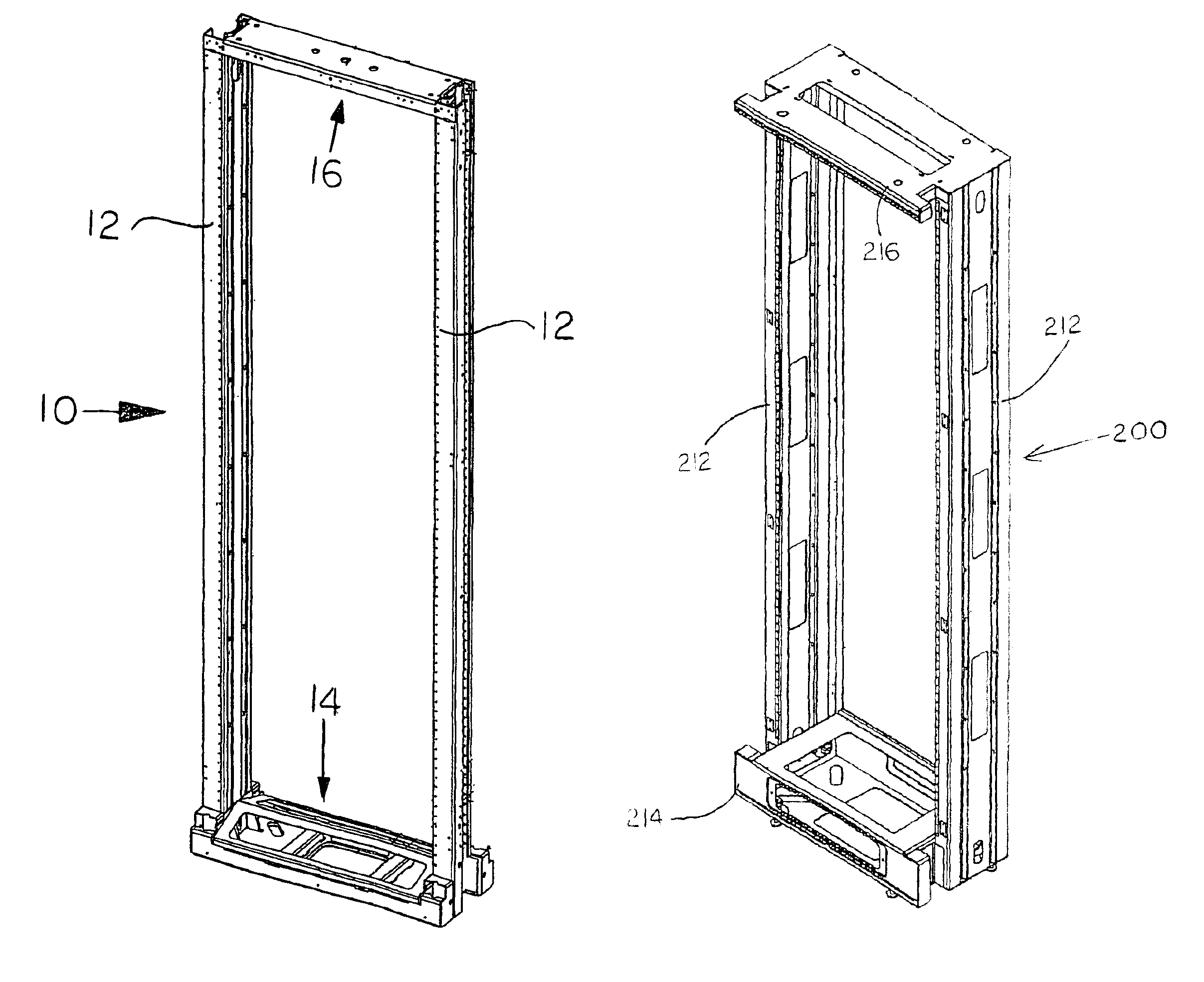
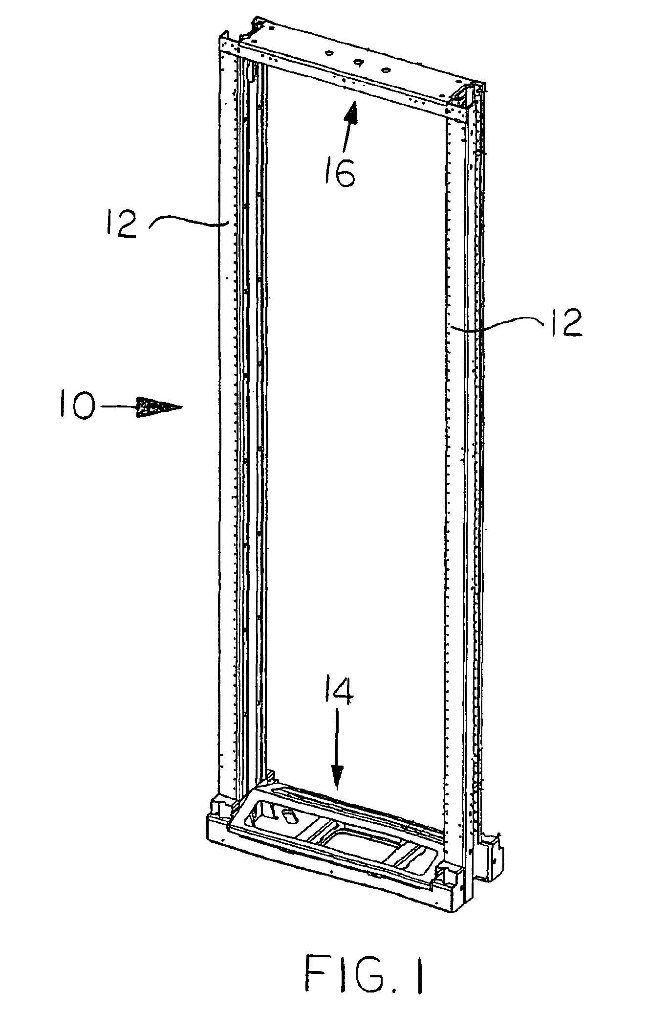
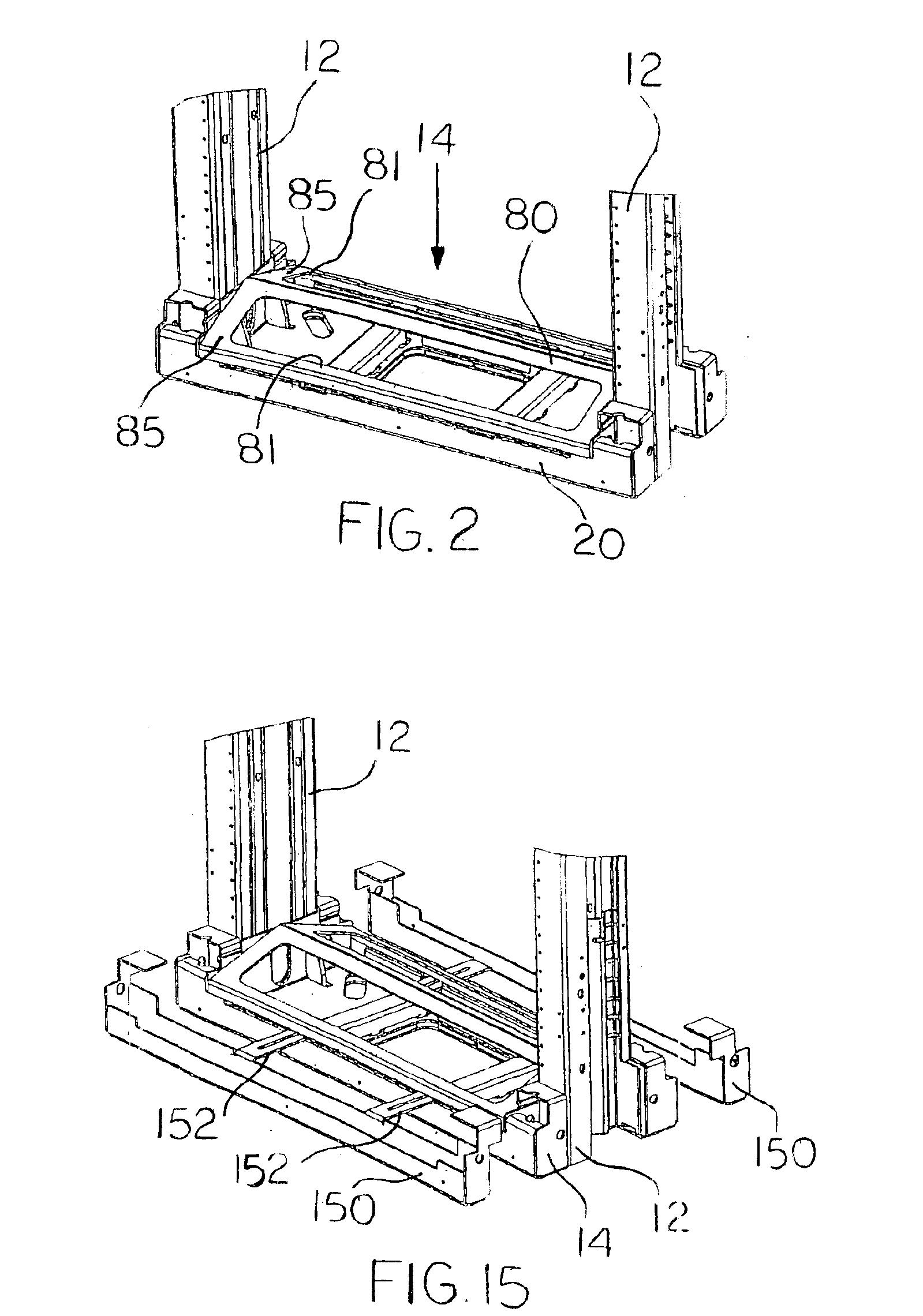
[0044]FIG. 1 shows an earthquake resistant equipment rack according to the present invention. The equipment rack 10 generally includes a base 14 and top 16 coupled by two side posts or rails 12. As shown in FIG. 3, the base 14 includes four main stacked components, an outer base 20, two base plates 40, an inner base 50 and a base box 60. These components are welded to another. The rails or vertical upright members 12 fit into notches 34 formed in the outer base 20 and the base plates 40. The rails 12 are also welded to the components of the base 14.

[0045]In addition, the outer base 20 includes four gussets 24, one at each corner of the outer base 20, and a front wall 28 and rear wall 29, all formed integrally with the outer base floor 21. A cable aperture 22 is positioned in the center of floor 21. A plurality of weld apertures 23 are provided in the outer base 20 and the inner base 50. These weld apertures 23 are used to plug weld one component to another. For example, the weld ape...

second embodiment

[0056]an earthquake resistant equipment rack is shown in FIGS. 19 through 26. Equipment rack is formed of a base 212 and top 216 attached by two side posts or rails 212. Base 214, top 216 and rails 212 are welded to one another. Base 214 includes a floor 220 with an integral upwardly extending back wall 222. Back wall 222 has a horizontally extending return 224 extending from its upper edge. Gussets are provided in each front corner of base 214. Each gusset includes an upwardly extending side 225 with a horizontally extending top 226 and a short return 217 extending downward from top 226. The base 214 includes level adjuster holes (not numbered), cable access aperture 22 and anchor bolts holes 31, similar to those described above for equipment rack 10.

[0057]A cover 230 is non-removably attached (preferably by welding) to base 214. Cover 230 includes a top with downwardly extending front and back walls, 232, 236 and downwardly extending side walls 237. Each side wall 237 has a cable ...


PUM


Abstract

An earthquake resistant equipment rack that includes multiple methods for reinforcing the equipment rack to resist seismic forces. The side rails can include two inwardly projecting V portions extending the length of the rails to diffuse seismic forces by deflecting seismic forces vertically. The base and top are preferably formed from multiple components formed from sheet metal and having both over-lapping multiple thickness of sheet metal and multiple box structures. A cover is non-removably attached to the base. In one embodiment, the cover has a dog house shape with inclined roof like surfaces.

Description

[0001]This application claims the benefit of U.S. provisional application Ser. No. 60 / 250,262, filed Nov. 30, 2000. Application Ser. No. 60 / 250,262 is hereby incorporated by reference.TECHNICAL FIELD[0002]The present invention relates generally to racks for electrical equipment and, more particularly, to a rack for electrical equipment that can withstand abnormal seismic activity typical of areas prone to earthquakes and other destructive natural phenomena.BACKGROUND OF THE INVENTION[0003]Preservation of electronic equipment during earthquakes and after shocks for the maintenance of communications and other purposes is a major concern of earthquake preparedness. As there is a critical need for communications immediately after an earthquake in a populated area, it is important for communications equipment to be able to withstand the most severe earthquakes or seismic shocks that can be expected to occur in the vicinity of such equipment.[0004]With the introduction of electronic and f...

Claims


Application Information

Patent Timeline
Patent Type & Authority Patents(United States)
IPC IPC(8): H05K7/18H02B1/54
CPCH02B1/54H05K7/183H02B1/30
Inventor HENDERSON, KEVIN R.
Owner CK ACQUISITION HLDG INC
Why Eureka
Try Eureka