Axial retention system and components thereof for a bladed rotor

a technology of axial retention and blades, which is applied in the direction of liquid fuel engines, vessel construction, marine propulsion, etc., can solve the problems of inordinately difficult to accommodate the separation of two or more blades without introducing excessive weight, cost or complexity into the engine, and preventing the separation of multiple blades. , the effect of preventing or minimizing damage to the hub and blades

Inactive Publication Date: 2005-10-04
RTX CORP
View PDF26 Cites 37 Cited by
  • Summary
  • Abstract
  • Description
  • Claims
  • Application Information

AI Technical Summary

Benefits of technology

[0013]The principal advantage of the invention is its ability to prevent the separation of multiple blades. A further advantage is the ability of the tiered spacer to prevent or minimize damage to the hub and blades during windmilling and during blade installation and removal.

Problems solved by technology

A separation event usually results from foreign object ingestion or fatigue failure.
Because the separated blade fragment can comprise a substantial portion of the entire blade, separation events are potentially hazardous and, although rare, must be safely accounted for in the design of the engine.
However it has proven inordinately difficult to accommodate the separation of two or more blades without introducing excessive weight, cost or complexity into the engine.
Windmilling rotational speeds are too slow to urge the blade attachment flanks centrifugally against the disk slot lugs.
As a result, the blade attachments repeatedly chafe against the surfaces of the hub slots causing accelerated wear of the blade attachments and the hub.
Since both the hub and blades are extremely expensive, accelerated wear is unacceptable to the engine owner.
Either way, excessive tightness complicates blade installation and removal.
Moreover, surfaces that slide relative to each other during blade installation or removal are susceptible to damage from abrasive contaminants that might be present on the surfaces.
Excessive tightness exacerbates the risk of damage.

Method used


Image

  • Axial retention system and components thereof for a bladed rotor
  • Axial retention system and components thereof for a bladed rotor
  • Axial retention system and components thereof for a bladed rotor

Examples


Embodiment Construction

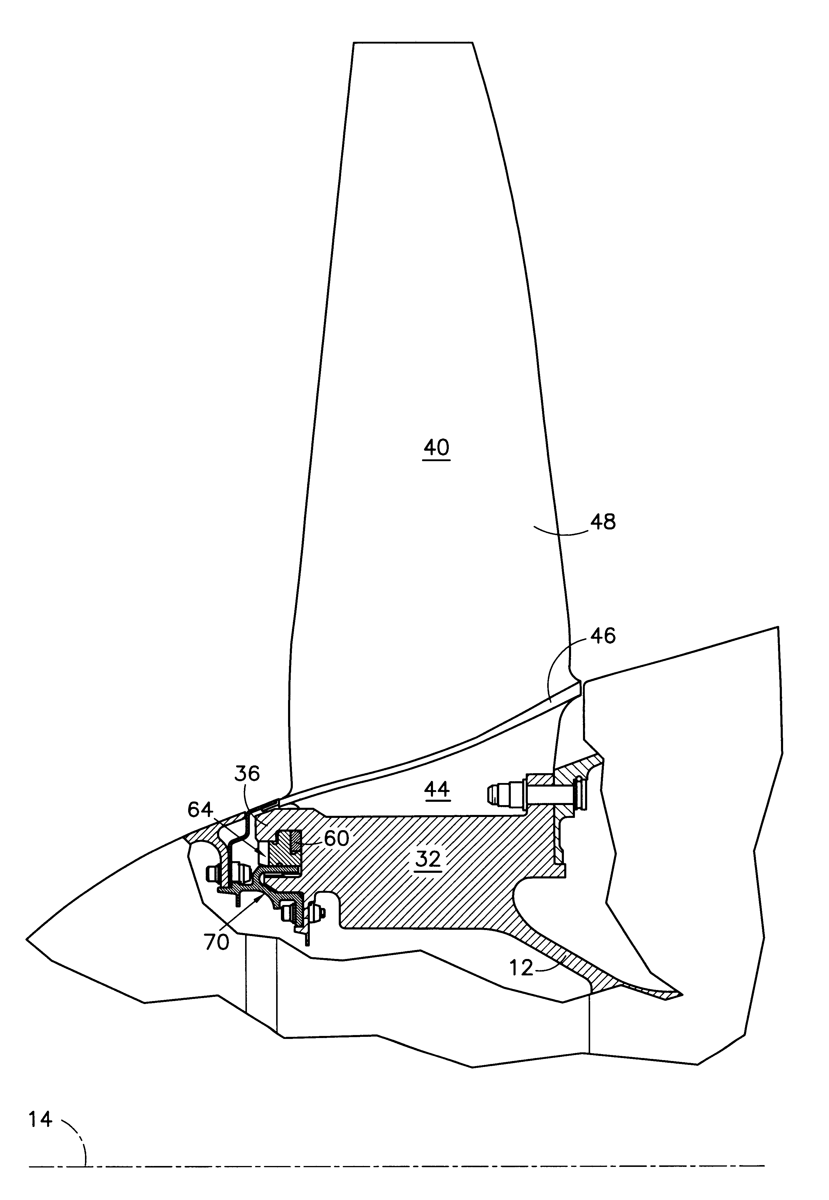
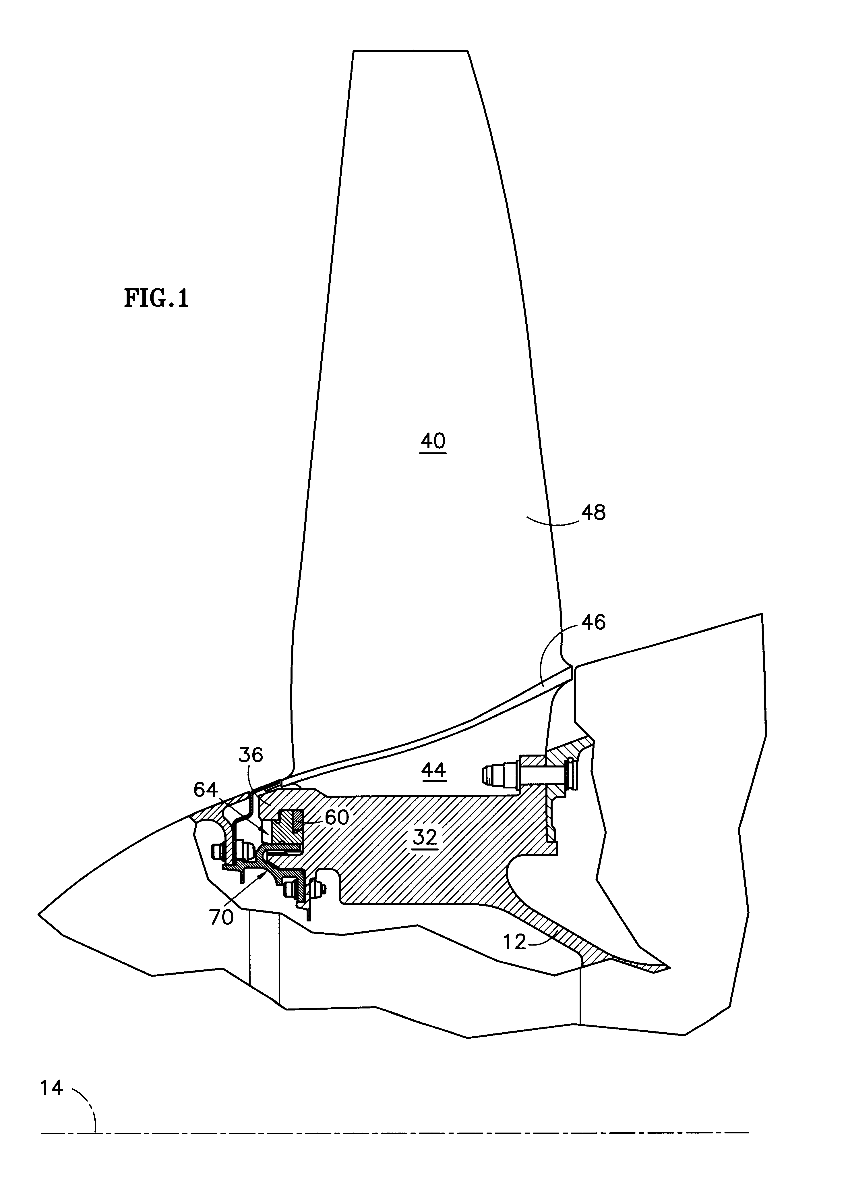
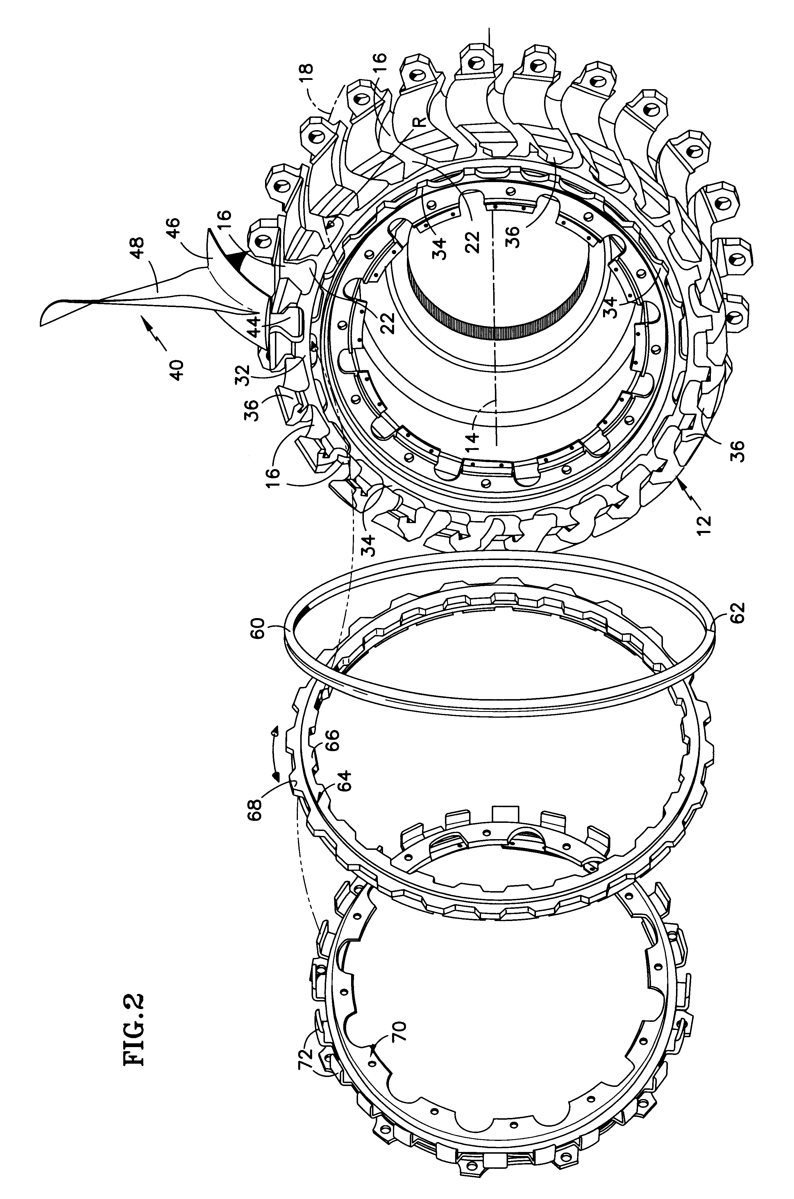
[0030]Referring principally to FIGS. 1 and 2, a fan rotor of an aircraft gas turbine engine includes a hub 12 rotatable about a rotational axis 14. The hub includes a series of circumferentially distributed peripheral slots 16. The illustrated slots, when viewed by an observer looking radially toward the axis, have a curved centerline 18 and a correspondingly curved profile. The centerline has a radius of curvature R. Alternatively, the slots may be linear slots having a linear centerline oriented parallel or oblique to the rotational axis. A slot opening 22 at the forward end of the hub, the aft end of the hub or both accommodates installation or removal of fan blades, described below, in the axial direction. As used throughout this specification, the term “axial” refers not only to a direction strictly parallel to the rotational axis but also to directions somewhat non-parallel to the axis, such as the slotwise direction defined by a curved or linear slot. As seen best in FIG. 9, ...


PUM


Abstract

A bladed rotor includes a hub 12 with bayonet hooks 34, 36, a bayonet ring 64 with bayonet projections 66, 68 that engage the hooks, and a load transfer element that occupies an annulus 38 defined by the hooks. Ideally, the load transfer element is a substantially circumferentially continuous snap ring 60. If a blade separation event or other abnormality exerts an excessive axial load on a blade, the snap ring 60 safely distributes that load to the bayonet hooks 34, 36 to prevent the blade from severing the snap ring and being ejected axially from its slot.

Description

CROSS REFERENCE TO RELATED APPLICATIONS[0001]This application includes subject matter in common with co-pending applications entitled “Chamfered Attachment for a Bladed Rotor”, application Ser. No. 10 / 123,453 and “Bladed Rotor with a Tiered Blade to Hub Interface”, application Ser. No. 10 / 123,549, both filed concurrently herewith, all three applications being assigned to or under obligation of assignment to United Technologies Corporation.TECHNICAL FIELD[0002]This invention relates to an axial retention system and components thereof for a bladed rotor, particularly a fan rotor of a gas turbine engine.BACKGROUND OF THE INVENTION[0003]A fan rotor of the type used in an aircraft gas turbine engine includes a hub capable of rotating about a rotational axis and an array of blades extending radially from the hub. The hub includes a series of circumferentially distributed peripheral slots. Each slot extends in an axial or predominantly axial direction and has a pair of overhanging lugs, ea...

Claims


Application Information

Patent Timeline
Patent Type & Authority Patents(United States)
IPC IPC(8): F01D5/00F01D5/30B64C11/04F01D5/32F04D29/34
CPCF01D5/323F01D5/326
Inventor DUESLER, PAUL W.ROSBOROUGH, RICHARDVUKOVINSKY, MICHAEL
Owner RTX CORP
Why Eureka
Try Eureka