
Method of baseband frequency hopping utilizing time division multiplexed mapping between a radio transceiver and digital signal processing resources

Active Publication Date: 2005-10-04
INTELLECTUAL VENTURES I LLC
View PDF10 Cites 21 Cited by
  • Summary
  • Abstract
  • Description
  • Claims
  • Application Information

AI Technical Summary

Benefits of technology

[0010]The present invention provides a method of performing frequency hopping with a wideband transceiver configured in a modular manner, by periodically changing the mapping between DSPs and their associated channels to comply with a frequency hopping schedule. The ability to freely allocate DSPs among channels, used to provide flexibility in handling changing traffic loads and the like, as will be described, is thus harnessed to provide frequency hopping modifications.
[0011]Specifically, frequency hopping reduces co-channel interference for each call by switching the frequency on which a particular traffic channel is transmitted. Thus, frequency hopping reduces the probability of RF interference events between co-channels. This allows improved call quality with more overall system capacity via higher frequency reuse. To further clarify, frequency hopping varies the frequency used at predetermined intervals and uses different hop sequences that are non-correlated between basestations using a subset of the same frequencies. Accordingly, the present invention supports frequency hopping utilizing real-time switching RF carriers over a time division multiplexed (TDM) bus between RF transceiver resources and digital signal processing resources.
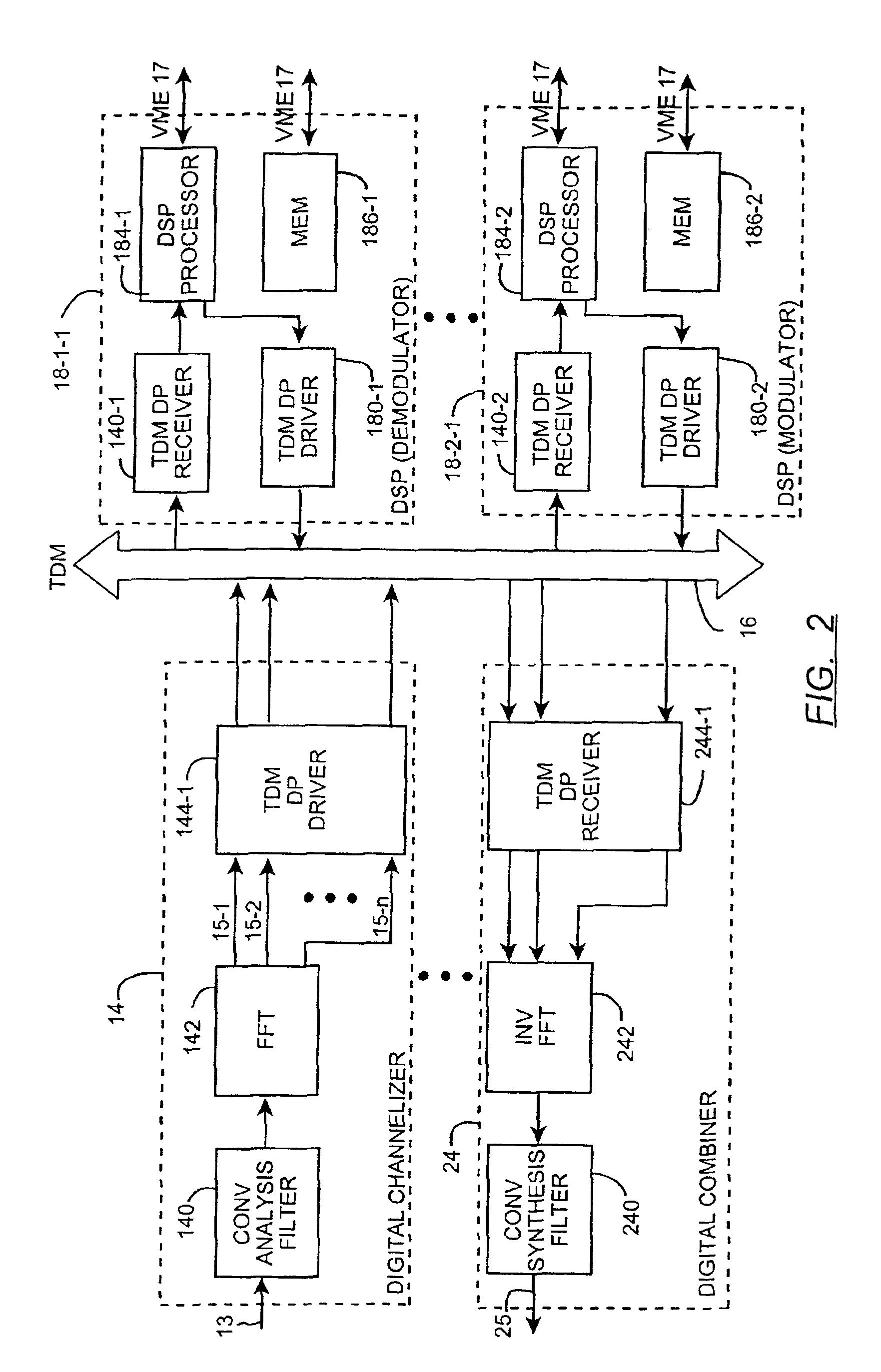
[0013]To support frequency hopping, as provided in GSM for example, the architecture of the present invention also allows determination of changes in the frequency and the ability to effect those changes in synchronization with a mobile unit. To effect these changes, the invention divides the DP-RAM into two sections. One section contains the current frequency set of all RF channels, and the other section contains the next frequency set in the hop sequence. This ping / pong structure of the DP-RAM allows a digital signal processor to swap the sections of the DP-RAM at predetermined intervals that are used to map RF channels to the TDM bus. The same DSP has access to the DP-RAM and fills the inactive section of the DP-RAM with the frequency information for the next frequency hop. Therefore, all swapping or ping / pongs of the DP-RAM occur at the frequency hop (FHOP) rate. Furthermore, the ping / pongs of the DP-RAM invoked by a DSP must be synchronized with other DSPs performing baseband processing of the RF channels as the FHOP rate is determined by the framing structure of the GSM TDMA RF (radio frequency) signal. One scheme used to achieve this synchronization is to align the GSM framing time of the DSP controlling the DP-RAM with baseband processing DSPs using a common TDMA frame signal generated by digital clocking logic and driven by an accurate timing source such as a global positioning system (GPS) receiver. All DSPs monitor this TDMA framing signal in the frequency hop mode, and via this architecture, frequency hopping is supported for the broadband basestation.
[0014]In accordance with the present invention, the co-channel interference associated with signal processing architectures currently employed by multichannel wireless communication service providers is reduced by this new and improved broadband architecture and methodology that supports frequency hopping.

Problems solved by technology

This is particularly true where relatively large, secure, and protective structures for multiple racks of equipment are not necessarily available or cost effective.

Method used


Image

  • Method of baseband frequency hopping utilizing time division multiplexed mapping between a radio transceiver and digital signal processing resources
  • Method of baseband frequency hopping utilizing time division multiplexed mapping between a radio transceiver and digital signal processing resources
  • Method of baseband frequency hopping utilizing time division multiplexed mapping between a radio transceiver and digital signal processing resources

Examples


Embodiment Construction

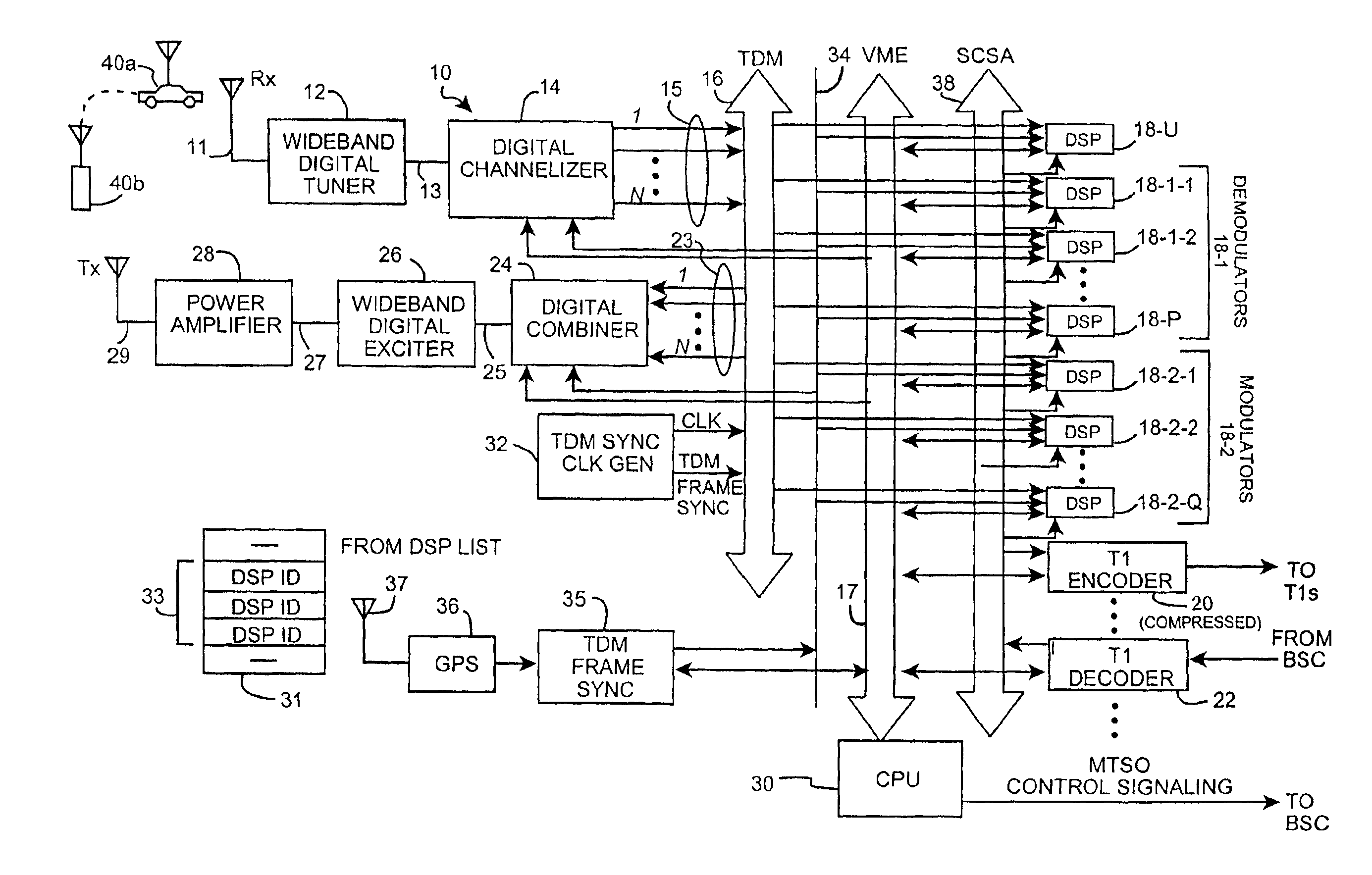
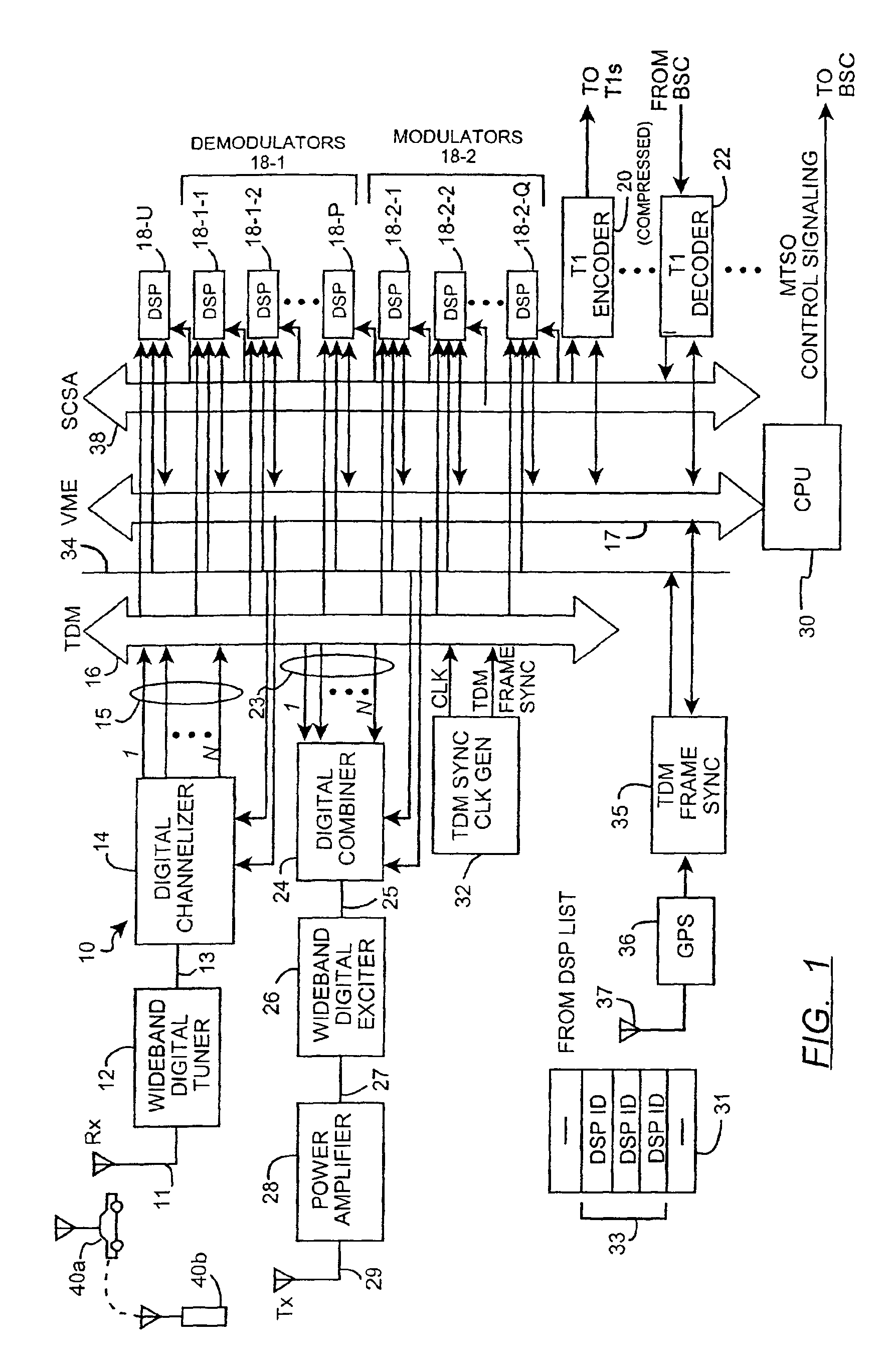
[0027]FIG. 1 is a block diagram of a wideband wireless digital basestation 10 according to the invention. Briefly, the basestation 10 consists of a receive antenna 11, one or more wideband digital tuners 12, one or more digital channelizers 14, a time division multiplex (TDM) bus 16, a control bus 17, a plurality of digital signal processors (DSPs), a first subset of which are programmed to operate as demodulators 18-1-1, 18-1-2, . . . , 18-1-P (collectively, demodulators 18-1); a second subset of which are programmed to operate as modulators 18-2-1, 18-2-2, . . . , 18-2-Q (collectively, modulators 18-2); and a third subset 18-U of which are presently idle, transport signal (T-1) encoder 20, a T-1 decoder 22, one or more digital combiners 24, one or more wideband digital exciters 26, a power amplifier 28, a transmit antenna 29, a basestation control processing unit (CPU) 30, a TDM bus synchronization clock generator 32, a signal computing system architecture (SCSA) bus 38, a TDMA fr...


PUM


Abstract

A method of frequency hopping is supported by a basestation having a broadband transceiver. The method permits changing physical channels upon which mobile subscribers communicate with the basestation, wherein the broadband transceiver is operated using static transceiver frequencies, the method exclusive of switching communication signals between transceivers. In one embodiment, the method maps baseband output signals from a digital channelizer which represent physical channels to ones of digital signal processors representing logical channels and baseband input signals of a digital combiner to ones of logical outputs of digital signal processors according to a mapping signal.

Description

[0001]This application claims the benefit of Provisional Application No. 60 / 104,422 filed Oct. 15, 1998.CROSS REFERENCE TO RELATED APPLICATIONS[0002]This application is related to and claims priority from U.S. patent application Ser. No. 09 / 418,629 entitled “BASESTATION ARCHITECTURE SUPPORTING BASEBAND FREQUENCY HOPPING UTILIZING TIME DIVISION MULTIPLEXED MAPPING BETWEEN A RADIO TRANSCEIVER” filed Oct. 15, 1999, the entirety of which is incorporated herein by reference. As filed, U.S. patent application Ser. No. 09 / 418,629 was entitled “METHOD OF BASEBAND FREQUENCY HOPPING UTILIZING TIME DIVISION MULTIPLEXED MAPPING BETWEEN A RADIO TRANSCEIVER AND DIGITAL SIGNAL PROCESSING RESOURCES”.FIELD OF THE INVENTION[0003]The present invention relates in general to wireless communication networks (e.g. cellular and personal communication systems) and is particularly directed to an architecture to support frequency hopping associated therewith.BACKGROUND OF THE INVENTION[0004]The basestations u...

Claims


Application Information

Patent Timeline
IPC IPC(8): H04Q7/30H04W88/08
CPCH04W88/08
Inventor SCHWALLER, JOHN F.SMITH, JEFFREY WILSONWILLIAMS, TERRY L.
Owner INTELLECTUAL VENTURES I LLC
Learn More