Battery grid

a battery grid and battery technology, applied in the field of battery grid modification, can solve the problems of lead-acid batteries failing in service, batteries having lead-antimony grids that require periodic maintenance, water loss due to gassing, etc., and achieve the effects of increasing the cycle life of batteries, enhancing adhesion, and increasing the formation efficiency of batteries

Inactive Publication Date: 2005-10-11
CPS TECH HLDG LLC
View PDF84 Cites 77 Cited by
  • Summary
  • Abstract
  • Description
  • Claims
  • Application Information

AI Technical Summary

Benefits of technology

[0020]It is therefore an advantage of the present invention to provide a method that increases the cycle life of a battery by enhancing the adhesion between the battery active material and the battery grid.
[0021]It is a further advantage to provide a method that increases the formation efficiency of a battery by enhancing the adhesion between the battery paste material and the battery grid.
[0022]It is yet another advantage to provide a method that can modify the shape of wires of a battery grid made from a continuous process so that the paste can flow around the grid wires to improve the plate strength.
[0023]It is still another advantage of the present invention to provide a method of making battery grids that allows a battery manufacturer to take advantage of a low cost continuous grid making process without the drawbacks associated with inadequate paste adhesion such as reduced formation efficiency and reduced cycle life.
[0024]It is yet another advantage of the present invention to provide a method of making battery plates or battery grids that produces a battery grid having increased grain size near the surface of the battery grid.
[0025]It is still another advantage of the present invention to provide a method of making battery plates or battery grids that produces a battery grid with increased surface area thereby increasing interfacial contact and mechanical bonding between the grid and battery paste.

Problems solved by technology

However, it was discovered that when a lead-antimony alloy is used in battery grids, water loss occurs because of gassing.
Therefore, batteries having lead-antimony grids required periodic maintenance, i.e., the addition of water to the battery.
It is well known that lead-acid batteries will eventually fail in service through one or more of several failure modes.
Among these failure modes is failure due to corrosion of the grid surface.
Electrochemical action corrodes the grid surface and reduces the adhesion between the active material and the grid.
In most instances, failure of the battery occurs when the grids are no longer able to provide adequate structural support or current flow due to the separation of the active material from the grid.
However, positive lead-acid battery plates made by a continuous plate making method underperform in service (cycle) life as compared to gravity cast book mold grids, especially in the high temperature environment under the hood of today's more compact cars.
In particular, lead-acid batteries having positive plates made by a continuous plate making method from lead-calcium alloys have proven to be relatively short-lived as determined by the SAE J240B Life Cycle Test (at 40° C. and particularly at 75° C.) owing to corrosion of the grid surface which forms an electrically resistive layer between the active material and the grid and seemingly reduces the adhesion between the active material and the grid over the course of the test.
Lead-calcium grid batteries are particularly susceptible to early failure for the high temperature (75° C.)
A low formation efficiency of positive plates requires a high formation charge.
Inefficient charging also leads to deficiencies in the resulting batteries assembled with such plates.
Typically, the initial capacity (performance) of the battery is low if the battery is not completely formed, requiring additional cycling to reach specific performance values.
However, all of the aforementioned methods have certain disadvantages that limit the ability of these methods to attain maximum effectiveness in improving battery service life.
Therefore, the beneficial effects of the alloy coating on paste adhesion and service life will be necessarily limited as the entire surface of the grid wires will not be coated.
In addition, the coating methods disclosed in U.S. Pat. No. 5,858,575 are used with expanded metal grids (as shown in FIG. 1 of U.S. Pat. No. 5,858,575) which are known to have inferior charge / discharge efficiency as compared to stamped grids, such as that shown in U.S. Pat. No. 5,989,749.
The decreased charge / discharge efficiency of the expanded grids also limits the service (cycle) life of a battery.

Method used


Image

  • Battery grid
  • Battery grid
  • Battery grid

Examples


example 1

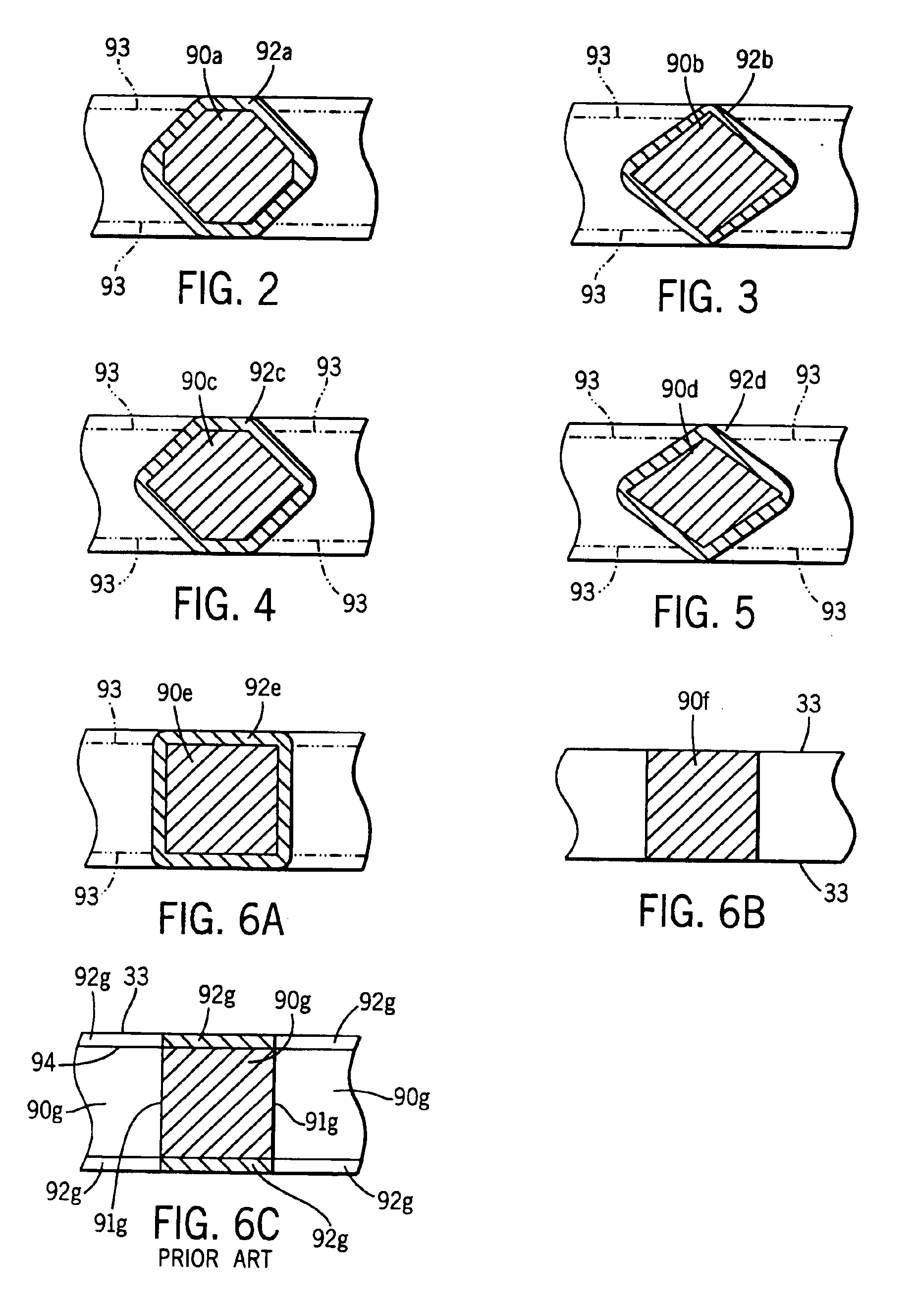
[0085]A continuous strip was prepared from a lead-alloy having the following composition: 0.0425 wt. % calcium, 0.925 wt. % tin, 0.013 wt. % aluminum, 0.0125 wt. % silver and balance lead. A series of interconnected battery grid shapes were then formed in the strip in a progressive punching operation, i.e., features were added to the battery grid through several punching operations. The battery grid wire sections of the strip were then processed in a coining station to coin the grid wires so that the grid wires had a cross-section similar to the grid wire cross-sections 90c in FIG. 4. The interconnected battery grids were then divided into individual grids. The grids were then pasted with a conventional battery paste and formed into battery cells. The battery cells were then cycled in accordance with the SAE J240 life test procedure at a temperature of 75° C. (167° F.) to measure the service life.

example 2

[0086]A continuous strip was prepared from a lead-alloy having the following composition: 0.0425 wt. % calcium, 0.925 wt. % tin, 0.013 wt. % aluminum, 0.0125 wt. % silver and balance lead. A series of interconnected battery grid shapes were then formed in the strip in a progressive punching operation, i.e., features were added to the battery grid through several punching operations. The battery grid wire sections of the strip were then processed in a coining station to coin the grid wires so that the grid wires had a cross-section similar to the grid wire cross-sections 90c in FIG. 4. The interconnected battery grids were then divided into individual grids. The grids were then hand dipped into a pot of molten 94 wt. % lead—6 wt. % tin coating alloy. The grids were dipped slowly into the melt until they bottomed out in the pot and then slowly withdrawn at the same rate for a total immersion time of about 2 seconds. The coating was uniform with no excess buildup on the grid wires or t...

example 3

[0087]A continuous strip was prepared from a lead-alloy having the following composition: 0.0425 wt. % calcium, 0.925 wt. % tin, 0.013 wt. % aluminum, 0.0125 wt. % silver and balance lead. A series of interconnected battery grid shapes were then formed in the strip in a progressive punching operation, i.e., features were added to the battery grid through several punching operations. The battery grid wire sections of the strip were then processed in a coining station to coin the grid wires so that the grid wires had a cross-section similar to the grid wire cross-sections 90c in FIG. 4. The interconnected battery grids were then divided into individual grids. The grids were then hand dipped into a pot of molten 94 wt. % lead—3 wt. % tin—3 wt. % antimony coating alloy. The grids were dipped slowly into the melt until they bottomed out in the pot and then slowly withdrawn at the same rate for a total immersion time of about 2 seconds. The coating was uniform with no excess buildup on th...


PUM

PropertyMeasurementUnit
weight percentaaaaaaaaaa
melting pointaaaaaaaaaa

Abstract

A method of forming battery grids or plates that includes the step of applying a lead alloy coating to a continuous strip of interconnected battery grids formed from a lead alloy grid material is disclosed. The battery grids may be formed by a continuous battery grid making process such as strip expansion, strip punching, or continuous grid casting. In one version of the method, the grid wires of a continuous strip of battery grids produced by a punching process are immersed in a melt of the lead alloy coating. In another version of the method, the grid wires of a continuous strip of battery grids produced by a punching process are deformed such that the grid wires have a cross-section other than the rectangular cross-section produced by the punching process and the strip of interconnected grids is immersed in a melt of the lead alloy coating. The method increases the cycle life of a battery.

Description

BACKGROUND OF THE INVENTION[0001]1. Field of the Invention[0002]The present invention relates to the modification of battery grids of the type used in lead-acid storage batteries, and more particularly, it relates to a modification of the surface finish of the battery grids of a lead-acid storage battery to improve paste adhesion and the service life of the battery.[0003]2. Description of the Related Art[0004]Lead-acid storage batteries typically comprise several cell elements which are encased in separate compartments of a container containing sulfuric acid electrolyte. Each cell element includes at least one positive plate, at least one negative plate, and a porous separator positioned between each positive and negative plate. The positive and negative plates each comprise a lead or lead alloy grid that supports an electrochemically active material. The active material is a lead based material (i.e., PbO, PbO2, Pb or PbSO4 at different charge / discharge stages of the battery) that ...

Claims


Application Information

Patent Timeline
Patent Type & Authority Patents(United States)
IPC IPC(8): H01M4/72H01M4/68H01M4/73H01M4/66H01M4/16H01M4/20H01M4/74C22C11/06H01M4/84
CPCH01M4/20H01M4/667H01M4/685H01M4/73H01M4/745Y10T29/49115Y02E60/126Y10T29/10Y10T29/49108Y02E60/10H01M4/82
Inventor CHEN, YU-LIN
Owner CPS TECH HLDG LLC
Why Eureka
Try Eureka