

Constant current supply device
a constant current supply and supply device technology, applied in the direction of electric variable regulation, process and machine control, instruments, etc., can solve the problems of circuit configuration complexity, reduced main current il, and increased manufacturing cost, so as to reduce the changes in controlled current
- Summary
- Abstract
- Description
- Claims
- Application Information
AI Technical Summary
Benefits of technology
Problems solved by technology
Method used
Image

Examples
first embodiment
(First Embodiment)
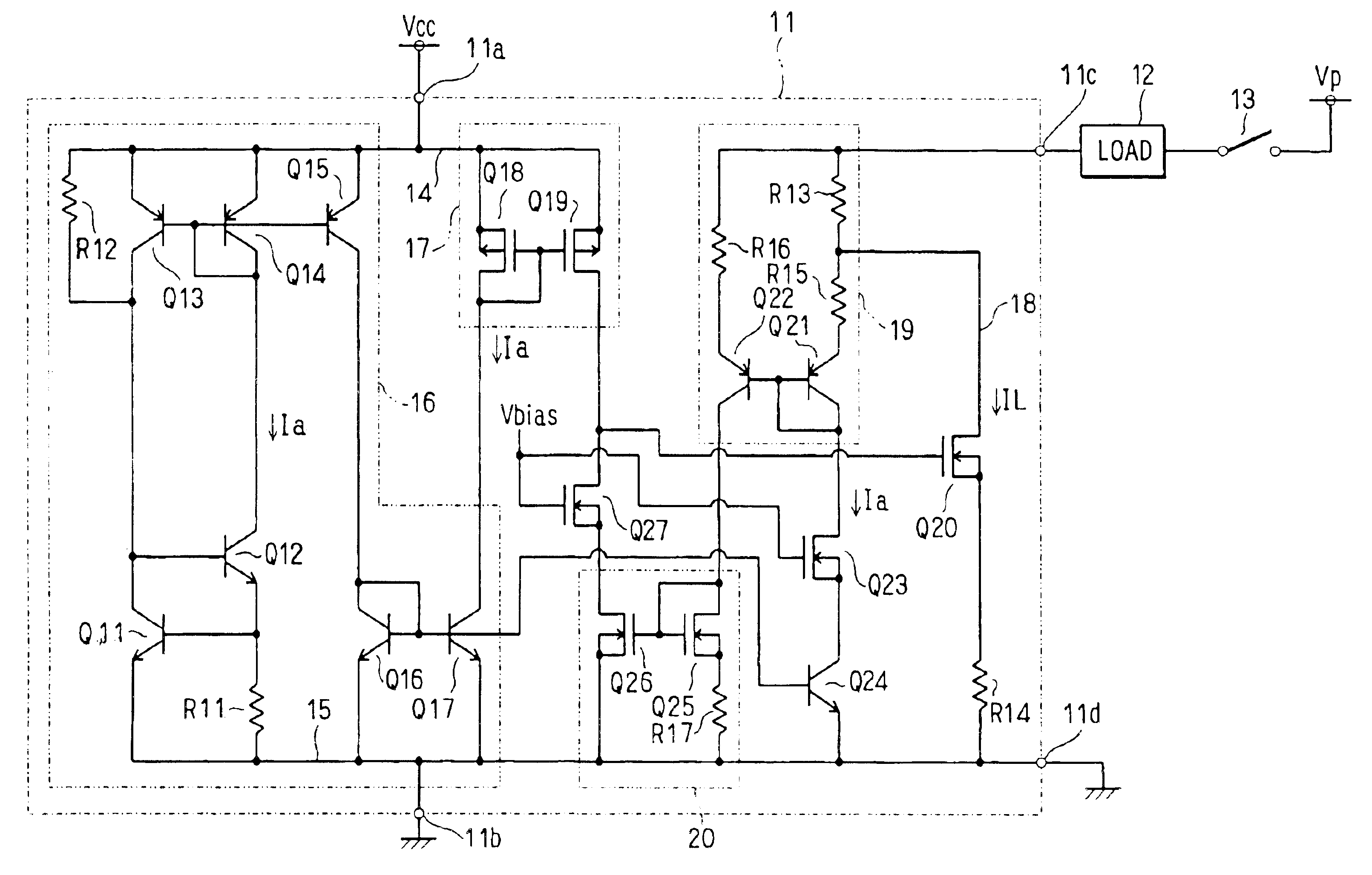
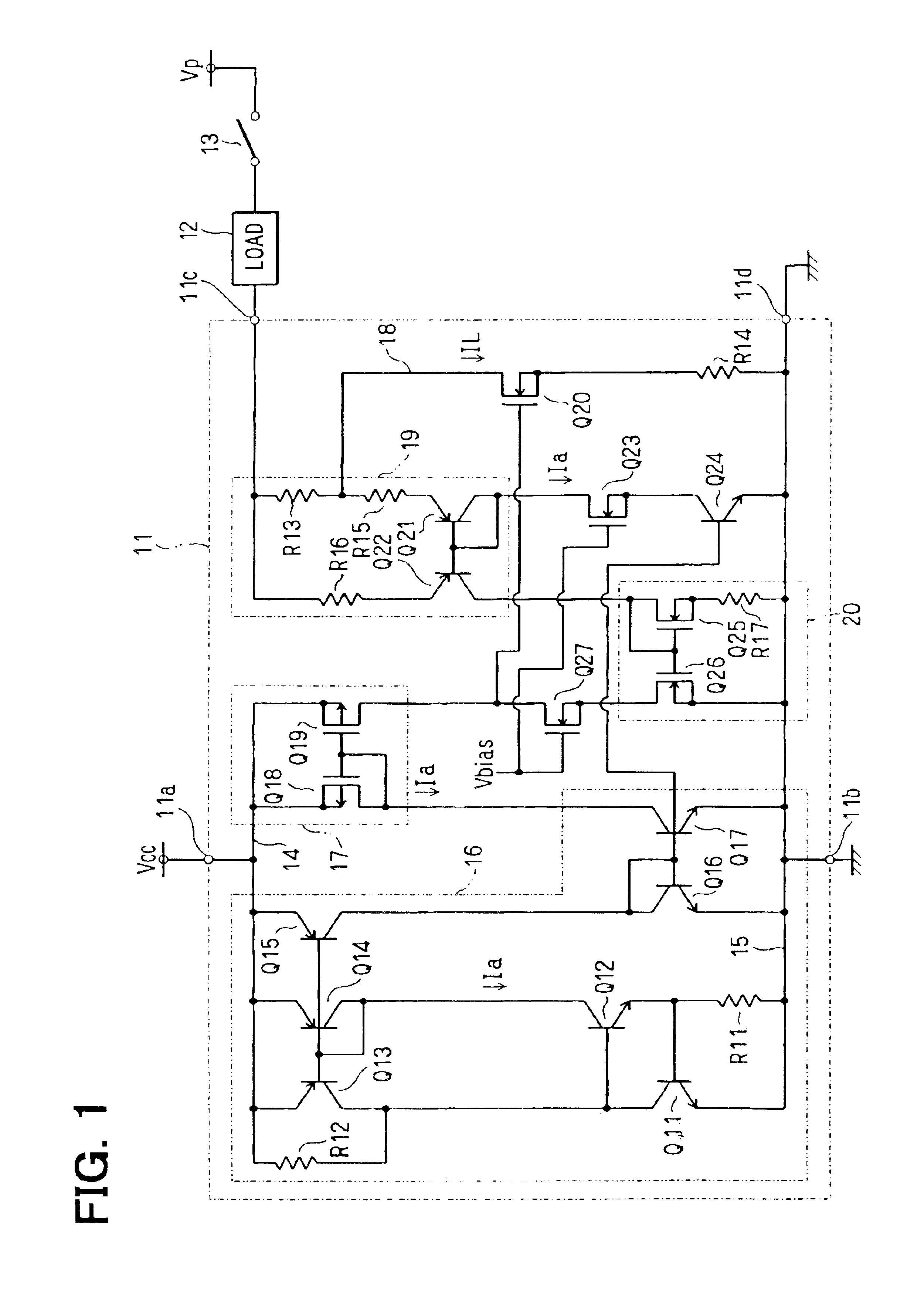
[0039]A constant current supply device 11 shown in FIG. 1 is an integrated circuit (IC) used typically for driving an airbag of an automobile. Terminals 11a and 11b of the IC 11 are each a power supply terminal. A power supply voltage Vcc of typically 25V is applied between the terminals 11a and 11b. A terminal 11c of the IC 11 is a current output terminal connected to one end of a load 12, the other end of which is connected to a voltage boosting power supply through a high-side switch circuit 13.
[0040]The voltage boosting power supply is for supplying a power supply voltage of typically 35V to the load 12 by way of the high-side switch circuit 13. The load 12 is a load to be borne in driving the airbag. The high-side switch circuit 13 is a semiconductor switching device. A terminal 11d of the IC 11 is the ground terminal of a power system supplying power to the terminal 11c. The constant current supply device 11 controls a current, which is flowing to the load 12...
second embodiment
(Second Embodiment)
[0066]A constant current supply device 21 shown in FIG. 4 is different from the constant current supply device 11 shown in FIG. 1 in that the constant current supply device 21 includes a resistor R18 (second compensation resistor) connected between the power supply line 14 and the source of the transistor Q19 to serve as a substitute for the resistor R17. The resistor R18 also has a positive temperature coefficient. In this case, the MOS transistors Q25 and Q26 form a current mirror circuit 22 (second current mirror circuit), whereas the MOS transistors Q18 and Q19 (fifth and sixth transistors) form a current mirror circuit 23 (third current mirror circuit) in conjunction with a resistor R18. It is to be noted that a constant current circuit 16 corresponds to a third constant current circuit.
[0067]In this configuration, it is assumed for example that the temperature of the IC 21 rises, causing the constant current Ia to decrease. In this case, the magnitudes of th...
third embodiment
(Third Embodiment)
[0075]FIG. 6 is a diagram showing an electrical configuration of a constant current supply device (IC) 211 having a plurality of current output terminals 212 corresponding to k channels and a plurality of constant current output circuits 213 each provided for one of the current output terminals 212. FIG. 7 is a diagram showing a detailed electrical configuration of each of the constant current circuits 212.
[0076]As shown in FIG. 6, the IC 211 comprises k current output terminals 212 and k constant current output circuits 213 each used for outputting a constant current of typically 1.3 A to an external load RL connected to one of the current output terminals 212. The remaining circuit shown in FIG. 6 is an output current adjustment circuit 214.
[0077]As shown in FIG. 7, in the constant current output circuit 213, a power supply line 215 (first power supply line) for supplying a battery voltage VMAIN in the range 5.6 to 35 V is wired to the emitter of a PNP-type trans...
PUM
 Abstract
Description
Claims
Application Information