

Multi-stage optical amplifier and broadband communication system
- Summary
- Abstract
- Description
- Claims
- Application Information
AI Technical Summary
Benefits of technology
Problems solved by technology
Method used
Image

Examples
Embodiment Construction
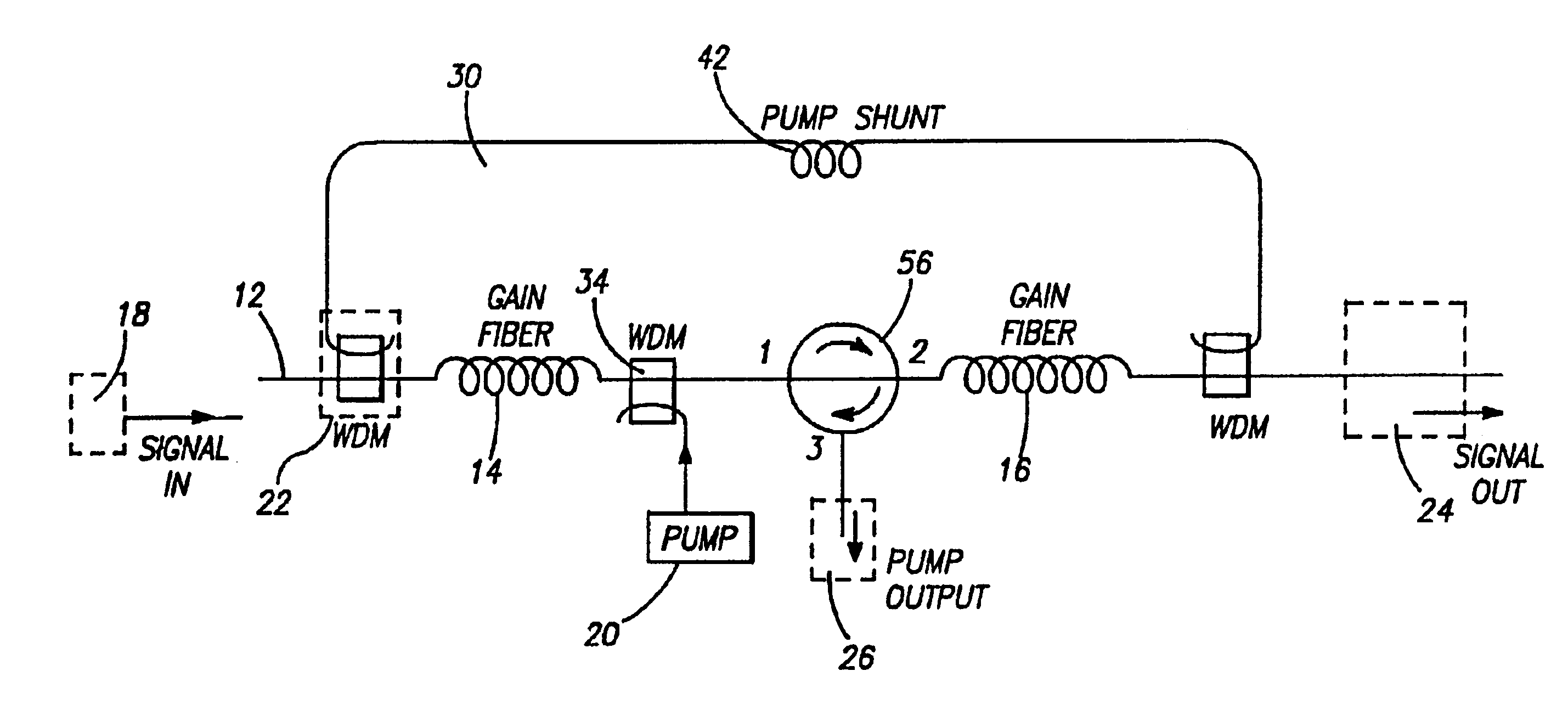
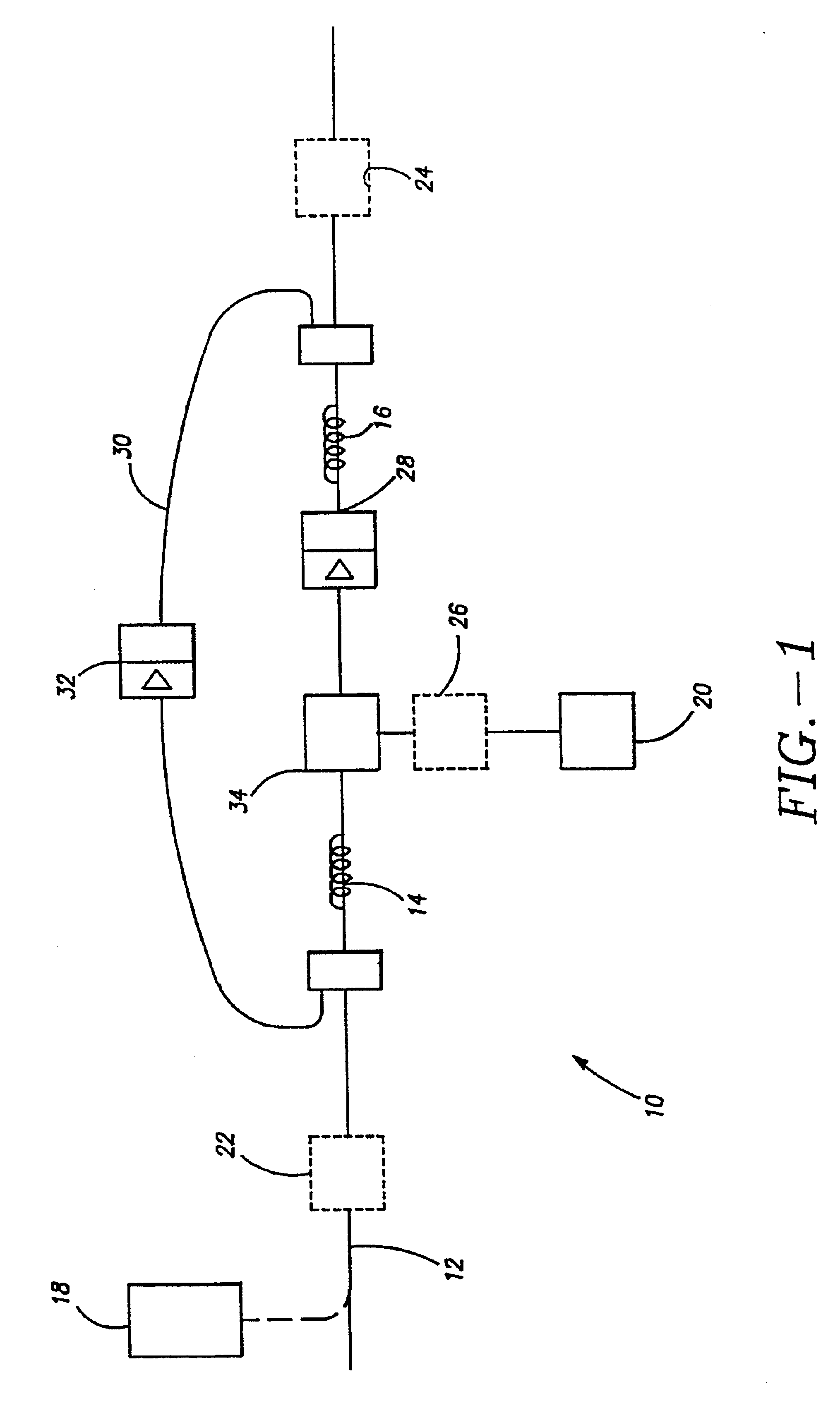
[0043]One embodiment of the present invention, as illustrated in FIG. 1, is a multi-stage optical amplifier 10 with an optical fiber 12 including a first length of amplifier fiber 14 and a second length of amplifier fiber 16. Optical fiber 12 is configured to be coupled to a signal source 18 that produces at least a signal wavelength λs and a pump source 20 that produces a pump wavelength λp. Pump wavelength λp is less than signal wavelength λs. Signal input port 22, signal output port 24 and pump input port 26 are each coupled to optical fiber 12. A first lossy member 28 is coupled to optical fiber 12 and positioned between the first and second lengths of amplifier fiber 14 and 16 respectively. A pump shunt 30 is coupled to signal input port 22 and signal output port 24. Optionally, a second lossy member 32 is coupled to pump shunt 30. Pump shunt 30 can be an optical fiber that is integral with optical fiber 12 or a separate optical fiber.
[0044]Pump beam λp propagates towards signa...
PUM
 Abstract
Description
Claims
Application Information