Synchronous rectification for low voltage motor drive

a low-voltage motor and synchronous technology, applied in the direction of electric variable regulation, process and machine control, instruments, etc., can solve the problems of reducing power dissipation, affecting the operation of the controller, and affecting the control of the switch, so as to improve the sensitivity of the circuit, enhance the operation of the circuit, and reduce the forward voltage drop of current

Inactive Publication Date: 2005-10-18
INTERNATIONAL RECTIFIER COEP
View PDF9 Cites 15 Cited by
  • Summary
  • Abstract
  • Description
  • Claims
  • Application Information

AI Technical Summary

Benefits of technology

[0005]According to the present invention, there is provided a circuit for measuring a voltage drop across a MOSFET to determine the direction of current flowing through the MOSFET. The voltage measurements across the MOSFET are introduced to a comparator that also has a special voltage input to produce a comparative result with the MOSFET voltage. An output of the comparator is coupled to the driver for the MOSFET to act in conjunction with the basic MOSFET driver command signals. The comparator output provides a signal that can indicate when the MOSFET should be conducting to turn ON the MOSFET channel and lower the forward voltage drop for current flowing through the channel. The comparator output signal also indicates when current through the MOSFET reduces to approximately zero and signals the MOSFET driver to turn OFF the MOSFET channel to permit the body diode of the MOSFET to block reverse current through the MOSFET.
[0006]By measuring the voltage across the MOSFET, and comparing the MOSFET voltage to a reference voltage, a signal is produced that provides an enhanced sensitivity for controlling the operation of a MOSFET as a synchronous rectifier. The circuit according to the present invention uses very few components and obtains a direct measurement across the MOSFET to enhance the operation of the circuit as a synchronous rectifier. According to an embodiment of the present invention, the input voltage across the MOSFET can be filtered before being supplied to the comparator to further enhance the sensitivity and noise immunity of the circuit.

Problems solved by technology

Thus, in many cases turning the channel ON causes a lower drop across the device, which in turn, reduces the power dissipation.
If switch S3 is not turned OFF when the current goes to zero, the current may then reverse in many applications (such as Switched Reluctance motors and trapezoidally wound and driven Brushless DC motors) and this can be harmful to the application.
In many applications, due to cost or technical reasons, it is difficult for the controller to know if the current has gone to zero to turn the switch S3 OFF.

Method used


Image

  • Synchronous rectification for low voltage motor drive
  • Synchronous rectification for low voltage motor drive
  • Synchronous rectification for low voltage motor drive

Examples


Embodiment Construction

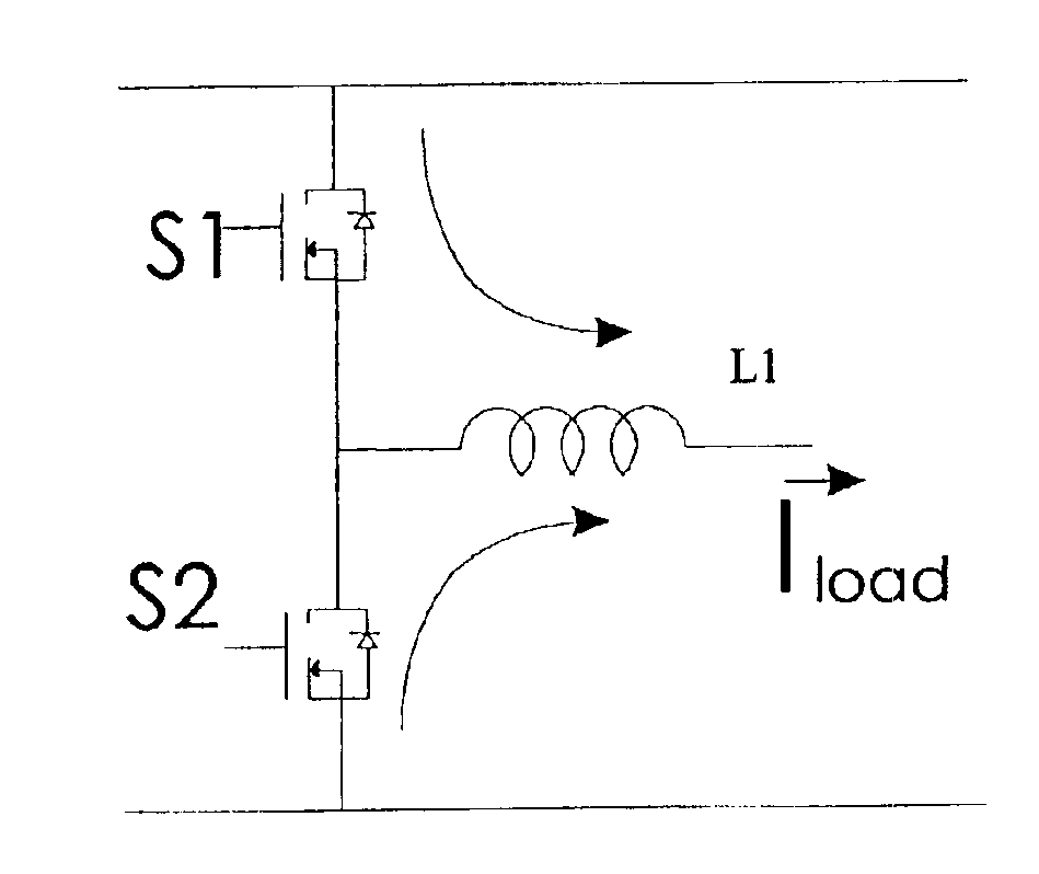
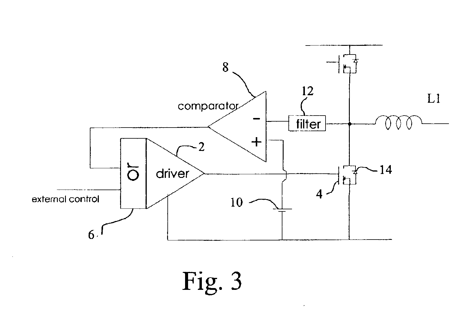
[0012]The present invention is shown in FIGS. 3 and 4, where the MOSFET driver 2 has the required intelligence to be able to autonomously turn the MOSFET 4 ON or OFF to take advantage of synchronous recirculation.

[0013]An OR circuit 6, a comparator 8, a reference voltage 10 and filter 12 are used with the driver to achieve the synchronous rectification function. It should be apparent that filter 12 varies depending upon the application, and may be eliminated altogether.

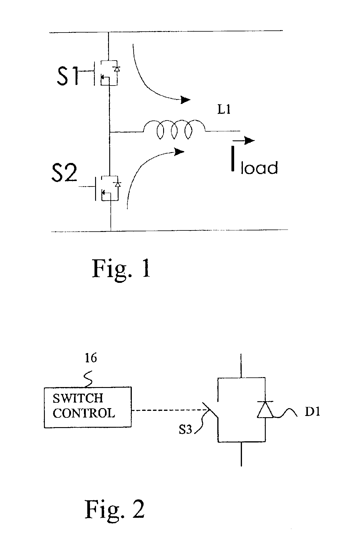
[0014]The function of additional elements is to turn MOSFET 4 ON when the voltage across it is below a preset reference voltage (in FIG. 2, reference voltage 10) which could be a low positive (about 0.5 v) or negative. This method takes advantage of the fact that the voltage across MOSFET 4 is low and in fact negative when the body diode 14 of MOSFET 4 is conducting. When comparator 8 senses that the voltage across MOSFET 4 has become negative, it concludes that diode 14 is ON and then turns ON the MOSFET channel. The...


PUM


Abstract

An inductive load driven by power MOSFETs, such as in a low voltage motor drive, using synchronous rectification to reduce the voltage drop across a body diode of a power MOSFET. A comparative feed back circuit measures voltage across the power MOSFET to determine when the body diode is conducting, and turns the MOSFET ON during conductive cycles, and OFF to block reverse current. The obtained synchronous rectification function is highly sensitive to current flow, while using a very small number of parts in a configuration that has less complexity.

Description

[0001]This application is based on and claims benefit of U.S. Provisional Application No. 60 / 327,792, filed Oct. 10, 2001, entitled SYNCHRONOUS RECTIFICATION FOR LOW VOLTAGE MOTOR DRIVE, to which a claim of priority is hereby made.BACKGROUND OF THE INVENTION[0002]Many power electronic applications have inductive loads that are driven by power MOSFETs. These MOSFETs are typically in a configuration shown in FIG. 1. When one of the MOSFETs (e.g., s1) is turned off, the inductive load causes the load current to flow through the internal diode of the second MOSFET (i.e., s2). These diodes, known as body diodes, have a minimum forward drop of about 0.6V. The MOSFET channel, however, due to its resistive characteristic, has a drop that is proportional to the current. Thus, in many cases turning the channel ON causes a lower drop across the device, which in turn, reduces the power dissipation.[0003]This method of using the channel to carry the reverse current flow is well known and is call...

Claims


Application Information

Patent Timeline
Patent Type & Authority Patents(United States)
IPC IPC(8): H02M3/158H02M3/04
CPCH02M3/1588H02M2003/1555Y02B70/1466Y02B70/10H02M3/1555
Inventor DUBHASHI, AJIT
Owner INTERNATIONAL RECTIFIER COEP
Why Eureka
Try Eureka