Broadband dual-polarized microstrip array antenna

a microstrip array, dual-polarized technology, applied in the direction of resonant antennas, individually energised antenna arrays, protective materials radiating elements, etc., can solve the problems of antenna bandwidth decline, system thickness, manufacturing cost increase, etc., and achieve the effect of reducing manufacturing cos

Inactive Publication Date: 2005-10-18
MISSION TELECOM +2
View PDF12 Cites 6 Cited by
  • Summary
  • Abstract
  • Description
  • Claims
  • Application Information

AI Technical Summary

Benefits of technology

[0007]The present invention was devised to solve the above-mentioned problems and it is an object of this invention to provide a broad-band dual-polarized microstrip array antenna having a parallel feeding type transmission line structure in order to decrease the manufacturing cost by using multiple films instead of a dielectric substrate and in order to generate separate polarization by separating a power supplying layer into two parts.

Problems solved by technology

Therefor the thickness of the system and the manufacturing cost increased.
Although the patch antenna has two exciting parts in case of using a single power supplying substrate, there is no sufficient space for arranging an exciting transmission line for another polarization, and the bandwidth of the antenna decreases in case of having a serial feeding type transmission line structure, and the transmission line structure becomes complicated and the bandwidth of the antenna decreases in case of having a mixing transmission line structure of the serial feeding type and the parallel feeding type.

Method used


Image

  • Broadband dual-polarized microstrip array antenna
  • Broadband dual-polarized microstrip array antenna
  • Broadband dual-polarized microstrip array antenna

Examples


Embodiment Construction

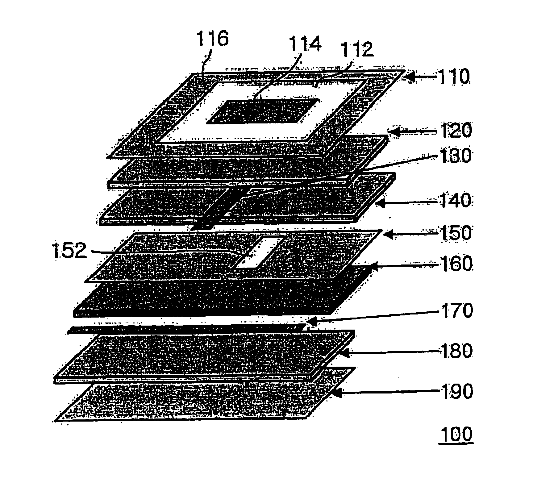
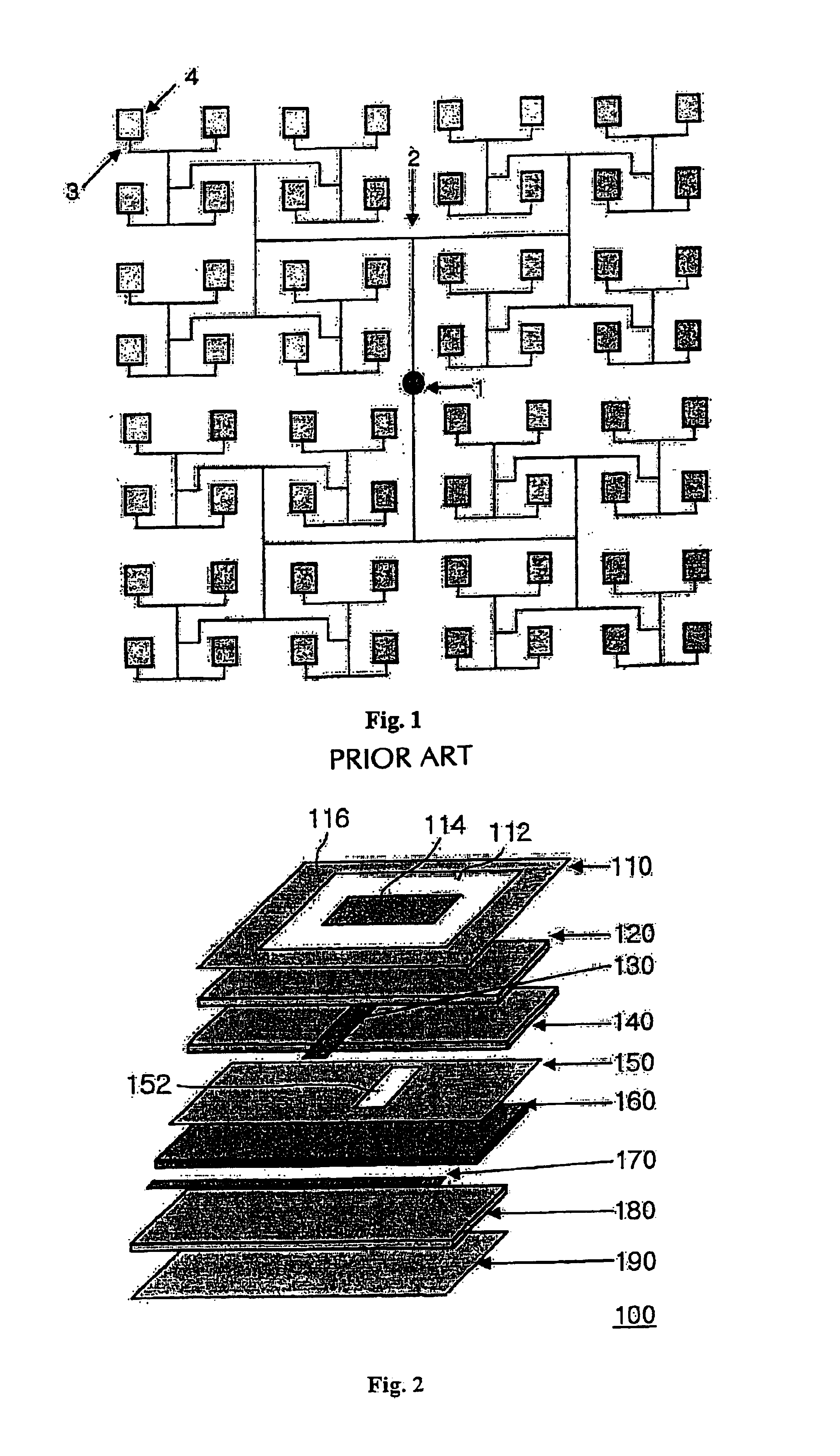
[0022]The broadband dual-polarized microstrip array antenna (100) according to the present invention is shown with reference to the FIG. 2.

[0023]The broad-band dual-polarized microstrip array antenna (100) comprises a first film (110), so called “ground”, coated with a metal on the upper side of a first film except the inner parts of closed regions (112), multiple of the closed regions arranged in uniform array forms. And the metal coated on the predetermined central regions of the closed regions (112) is removed and patch antenna (114) is formed on the removed central regions of the closed regions (112) and also on the outside region of the closed regions (112) in a first film (110).

[0024]In the present invention, the “film” means a thin vinyl film on which metal is coated and its price is cheaper than the traditional dielectric substrate by about 20%.

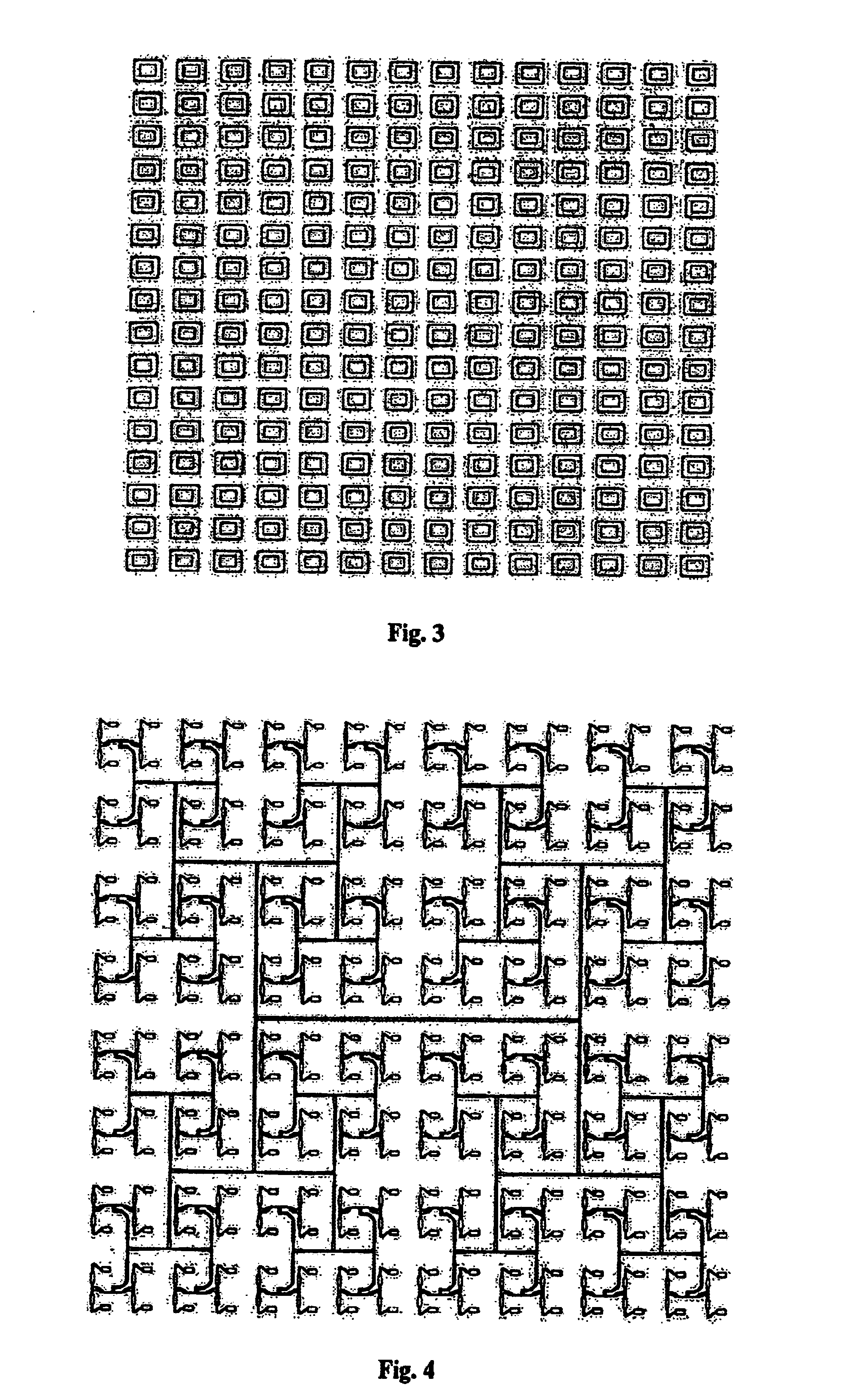
[0025]The FIG. 3 illustrates a patch antenna layer forming multiple patch antennas having the same structure as it of a first film o...


PUM


Abstract

This invention relates to a microstrip array antenna, especially a broad-band dual-polarized microstrip array antenna having parallel feeding structure whose consist of two parts power supplying layers each of which generates its own polarization respectively. And the broad-band dual-polarized microstrip array antenna according to the present invention arranges transmission paths for two separate linear polarization on a different layer each other in order to minimize an interference effect and a proximity feeding method and an aperture coupled method are used in order to get two separate polarization.

Description

BACKGROUND OF THE INVENTION[0001]1. Field of the Invention[0002]This invention relates to a microstrip array antenna, especially a broad-band dual-polarized microstrip array antenna having parallel feeding structure whose consist of two parts power supplying layers each of which generates its own polarization respectively.[0003]The broad-band dual-polarized microstrip array antenna according to the present invention arranges transmission paths for two separate linear polarization on a different layer each other in order to minimize an interference effect and a proximity feeding method and an aperture coupled method are used in order to get two separate polarization.[0004]2. Description of the Related Arts[0005]The general microstrip array antennas have used a dielectric substrate as a power supplying substrate having a power supplying line. Therefor the thickness of the system and the manufacturing cost increased. Also, it was possible to receive only one polarization because a patc...

Claims


Application Information

Patent Timeline
Patent Type & Authority Patents(United States)
IPC IPC(8): H01Q9/04H01Q21/06H01Q1/38H01Q13/08H01Q1/40H01Q13/10
CPCH01Q9/0457H01Q21/065
Inventor LEE, BYUNG-JEKANG, GI-CHOLEE, HAK-YONGKIM, NAM-YOUNGKIM, JONG-HEONLEE, GUEN-HORA, KEUK-HWAN
Owner MISSION TELECOM
Why Eureka
Try Eureka