Multi-beam scanner, multi-beam scanning method, synchronizing beam detecting method and image forming apparatus

a multi-beam scanner and beam detection technology, applied in the field of multi-beam scanners, can solve the problems of increasing the cost of the relevant multi-beam scanner, affecting the quality of achromatism-processed scanning optical systems, and the inability to mitigate the phenomenon of vertical line fluctuation

Inactive Publication Date: 2005-10-18
RICOH KK
View PDF31 Cites 25 Cited by
  • Summary
  • Abstract
  • Description
  • Claims
  • Application Information

AI Technical Summary

Benefits of technology

[0012]Accordingly, preferred embodiments of the present invention provide a novel multi-beam scanning apparatus and a novel multi-beam scanning method that effectively mitigate the phenomenon of vertical line fluctuation due to the difference in the wavelength of light emitted from the light source in multi-beam scanning.
[0013]According to a preferred embodiment of the present invention, a method of detecting a synchronizing beam for controlling optical write-in starting of each beam for scanning each scanning line in a multi-beam scanner includes the steps of: deflecting each of beams, emitted from a plurality of light sources and modulated independently according to an image signal, by a common deflector at an equiangular velocity toward an optical write-in starting portion of a scanned surface, and converging the deflected beam toward the scanned surface by a scanning image-forming optical system including lenses to form a plurality of light spots on the scanned surface, separated from each other in a sub-scanning direction, to simultaneously scan a plurality of scanning lines by use of the plurality of light spots; and sequentially guiding each deflected beam by a synchronizing beam optical system of a synchronization detecting system toward a light receiving device of the synchronization detecting system so as to be received by the light receiving device as the synchronizing beam, the synchronization detecting system reducing the value of a parameter d1 / ω1, where d1 is a maximum shift in a beam position in a main scanning direction at a light receiving face position of the light receiving device, caused by a difference in inter-beam wavelength in a synchronizing beam detecting view angle, and ω1 is a beam displacement at the light receiving face position corresponding to a unit change in a view angle of the synchronizing beam detecting view angle.

Problems solved by technology

An achromatism-processed scanning optical system, however, is expensive in manufacturing costs and so contributes to increased costs of the relevant multi-beam scanner as a whole.
Hei 9-76562, by which, however, the vertical line fluctuation which is caused by the difference in the emitted light wavelengths of the combined beams cannot be mitigated further.

Method used


Image

  • Multi-beam scanner, multi-beam scanning method, synchronizing beam detecting method and image forming apparatus
  • Multi-beam scanner, multi-beam scanning method, synchronizing beam detecting method and image forming apparatus
  • Multi-beam scanner, multi-beam scanning method, synchronizing beam detecting method and image forming apparatus

Examples


first embodiment

[0122][First Embodiment]

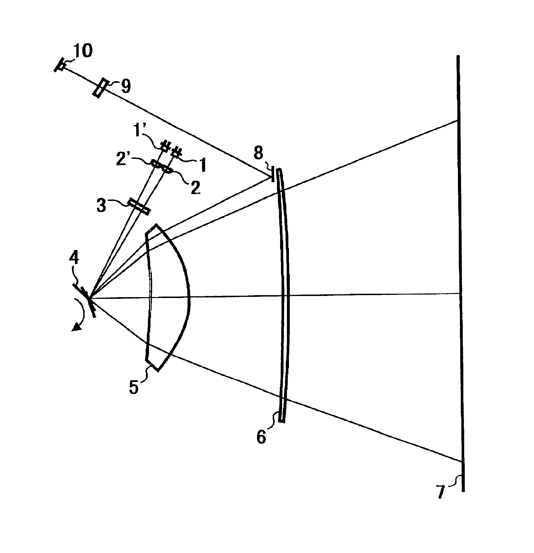
[0123]The multi-beam scanner illustrated in FIG. 7A is changed into a scanner as illustrated in FIG. 1. The specific data of both the optical system ranging from the light sources 1 and 1′ to the rotary multi-facial mirror 4 and the scanning lenses 5 and 6 constituting the scanning image-forming optical system is the same as the above-mentioned data.

[0124]Unlike the background art example, in the first embodiment, a deflected beam to be detected as a synchronizing beam passes through the scanning lens 5 and is then guided to the light receiving element 10 without passing through the scanning lens 6. That is, a deflected beam to be received by the light receiving element 10 passes through the scanning lens 5 but not through the scanning lens 6 and is turned back at the mirror 8 to be guided to the light receiving element 10. The light receiving element 10 is arranged near an image forming point (i.e., image forming point by the scanning lens 5) in the main sca...

second embodiment

[0141][Second Embodiment]

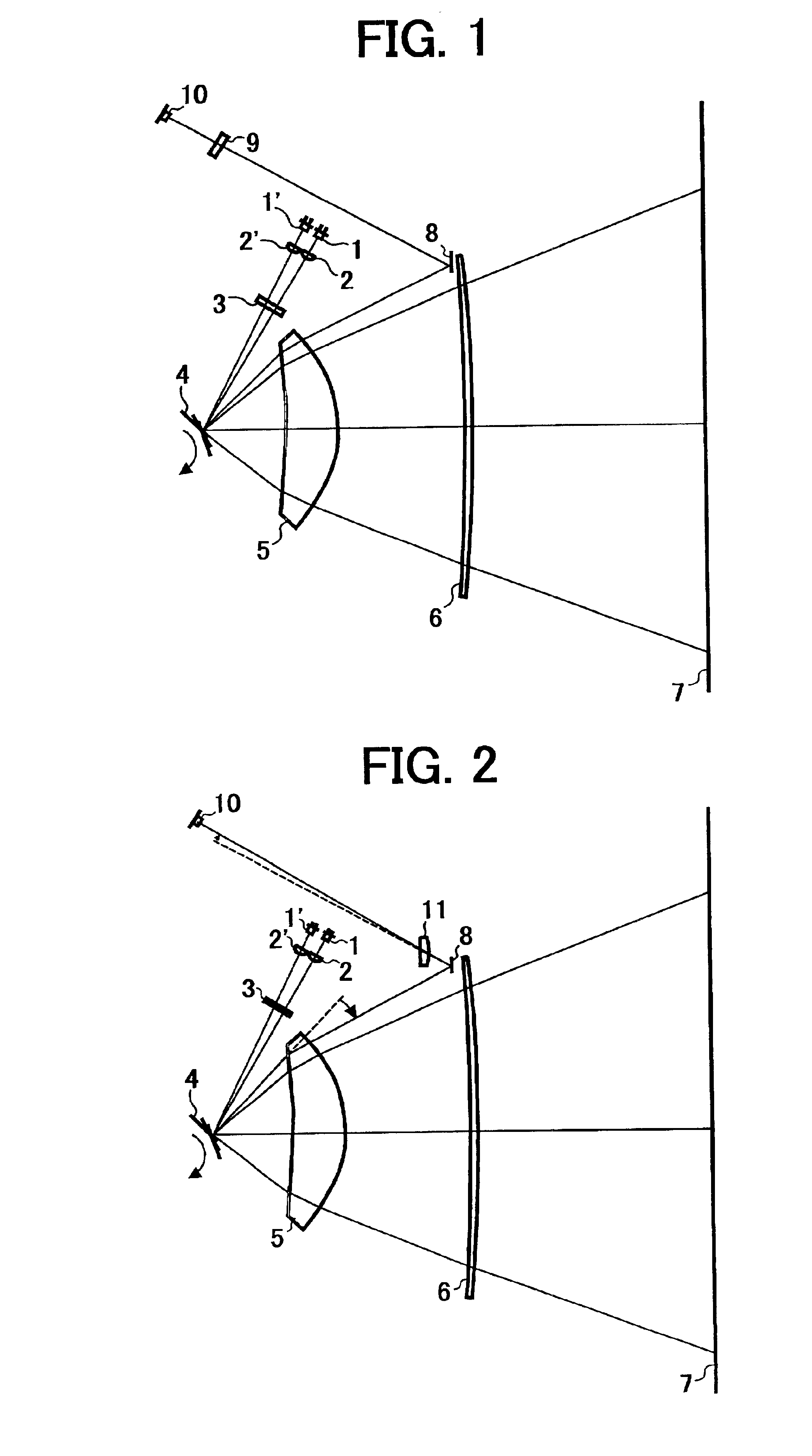
[0142]The multi-beam scanner shown in FIG. 7A has been changed to the scanner as illustrated in FIG. 2. The specific data of both the optical system ranging from the light sources 1 and 1′ to the rotary multi-facial mirror 5 and the scanning lenses 5 and 6 constituting the scanning image-forming optical system is the same as that mentioned above.

[0143]A deflected beam to be detected by the light receiving element 10 passes through the scanning lens 5 but not through the scanning lens 6 to be turned back at the mirror 8 and then is guided to the light receiving element 10 via a converging lens 11 arranged distant from the scanning lens 5 by 196.1 mm calculated as an optical path.

[0144]The converging lens has the following parameters:[0145]Main scanning directional shape of the incidence side face: arc with a curvature radius of 100 mm[0146]Main scanning directional shape of the emission side: curvature radius of[0147]Center thickness: 6 mm[0148]Refractive ind...

third embodiment

[0164][Third Embodiment]

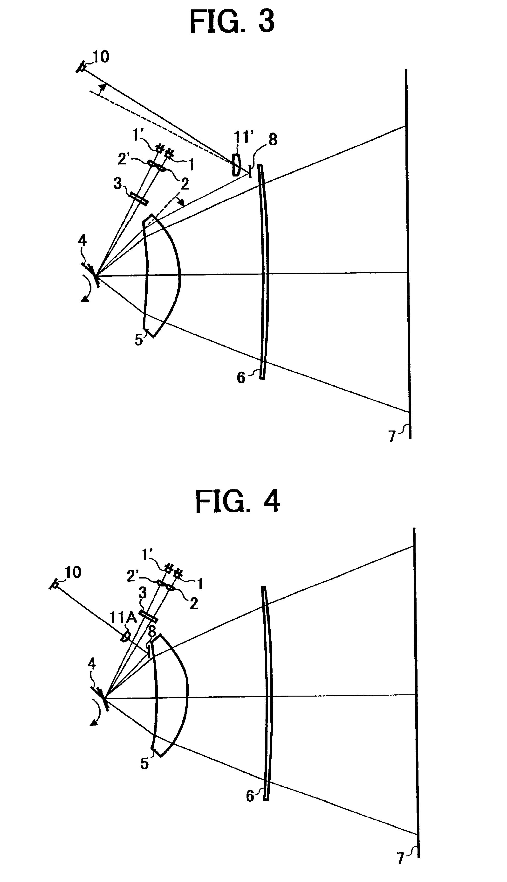
[0165]The multi-beam scanner illustrated in FIG. 7A has been changed to the scanner as illustrated in FIG. 3. The specific data of both the optical system ranging from the light sources 1 and 1′ to the rotary multi-facial mirror 4 and the scanning lenses 5 and 6 constituting the scanning image-forming optical system is the same as that mentioned above.

[0166]A deflected beam to be detected by the light receiving element 10 passes through the scanning lens 5 but not through the scanning lens 6 to be turned back at the mirror 8 and then is guided to the light receiving element 10 via a prism 11′ arranged distant from the scanning lens 5 by 197.4 mm calculated as an optical path.

[0167]The prism 1′ is constructed as follows.

[0168]Its incidence side face is inclined 18° in a plane parallel to the figure (i.e., plane parallel to both the main scanning direction and the optical axis of the scanning lenses 5 and 6). Its emission side face is perpendicular to the optic...


PUM


Abstract

A multi-beam scanner includes light sources, a deflector deflecting the beams emitted from the light sources at an equiangular velocity, a scanning image-forming optical system guiding the deflected beams to a surface so as to be formed into light spots on the scanned surface, a light receiving device receiving the beams deflected toward optical write-in starting portions on the scanned surface as synchronizing beams, and a synchronizing beam optical system guiding the beams deflected toward the optical write-in starting portions on the scanned surface to the light receiving device. The scanning image-forming optical system includes two or more scanning positive lenses, with a region having a positive power in a main scanning direction on an optical write-in starting side, and each deflected beam received by the light receiving device passes through one or more but not all of the scanning positive lenses to be guided to the light receiving device. An optical path length from the deflector to the light receiving device is set larger than an optical path length from the deflector to the scanned surface in the synchronizing beam optical system.

Description

CROSS-REFERENCE TO RELATED APPLICATIONS[0001]The present application claims priority from Japanese Patent Application No. 2000-148056: filed in the Japanese Patent Office on May 19, 2001, the contents of which is hereby incorporated by reference in its entirety.BACKGROUND OF THE INVENTION[0002]1. Field of the Invention[0003]The present invention relates to a multi-beam scanner, a multi-beam scanning method, a method for detecting a synchronizing beam in multi-beam scanning, and an image forming apparatus.[0004]2. Discussion of the Background[0005]There has recently appeared a multi-beam scanning method for light scanning that can meet requirements for increasing speed in light scanning.[0006]The multi-beam scanning method employs a plurality of light sources which can be independently modulated according to an image signal. Typically, one of those light sources may be a semiconductor laser where the emitted light wavelength varies slightly over different production lots of the laser...

Claims


Application Information

Patent Timeline
Patent Type & Authority Patents(United States)
IPC IPC(8): B41J2/44B41J2/47G02B13/00G02B13/18G02B26/10H01S5/40H04N1/113
CPCB41J2/473G02B26/123G02B26/125Y10S359/90
Inventor HAYASHI, YOSHINORI
Owner RICOH KK
Why Eureka
Try Eureka