
Integrated optical lightguide device

Inactive Publication Date: 2005-10-18
UNIVERSITY OF TWENTE
View PDF16 Cites 8 Cited by
  • Summary
  • Abstract
  • Description
  • Claims
  • Application Information

AI Technical Summary

Benefits of technology

[0012]Although the changes may be relatively small in the case of a single transition, the use of many transitions succeeding each another in the direction of light propagation may produce significant effects. Essential in this respect is that repetition of the transitions, and thus of the segments of parameter sensitive material or sensor material, does not need to be periodical because the operating principle is not based on phase information of the light being used, although a device according to the invention may use periodically repeated segments.
[0027]The bridge material for a lightguide used to measure relative humidity may include SiON having a refractive index of 1.50, and a material sensitive to air humidity may begelatin having a refractive index range of 1.53–1.47 in the air humidity range of 0–100%. By increasing the number of segments it is possible, using the same materials, to obtain excellent sensitivity to air humidity over a smaller part of the refractive index range to be measured around the air humidity value which corresponds with a gelatin refractive index of 1.50. This is sometimes called a peak response and it may be used as a switching pulse in an electronic circuit designed for that purpose. The selection of a refractive index of 1.53 for the bridge material makes it possible to measure refractive index values in the range of 1.52–1.53 with great precision. This range corresponds with an air humidity between of 90–100%. A chemical sensor giving peak responses may be useful for measuring the composition of a liquid or a gas mixture for the purpose of checking chemical processes, or for use in alarm systems to signal the exceeding of humidity limits, or to signal the occurrence of undesirable air or water pollution.

Problems solved by technology

Generally, such a device is much too complicated for practical applications and also relatively costly, and in some cases it is sensitive to interfering parameters or to small deviations between intended and realised local refractive index profiles.
For the lightguide structures to be used this means that transitions to and from elements in the optical structure will have to be provided very gradually in the direction of light propagation, resulting in relatively long structures.
This patent illustrates the use of segments of identical length which are periodically spaced, but is otherwise very limited in application.

Method used


Image

  • Integrated optical lightguide device
  • Integrated optical lightguide device
  • Integrated optical lightguide device

Examples


Embodiment Construction

[0059]While the present invention is open to various modifications and alternative constructions, the preferred embodiments shown in the various figures of the drawing will be described herein in detail. It is understood, however, that there is no intention to limit the invention to the particular embodiments, forms or examples disclosed. On the contrary, the intention is to cover all modifications, equivalent structures and methods, and alternative constructions falling within the spirit and scope of the invention as expressed in the appended claims, pursuant to Title 35 U.S.C. section 112 (second paragraph).

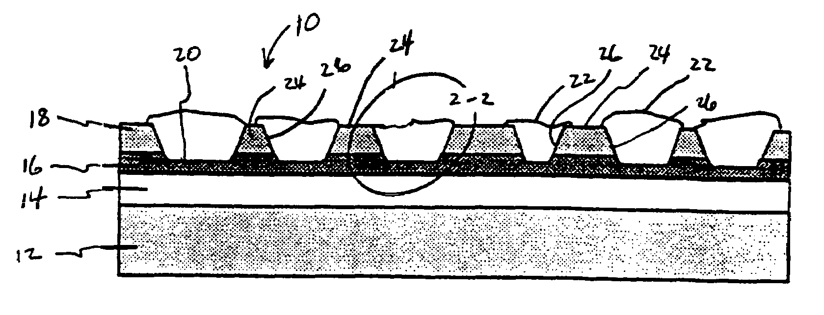
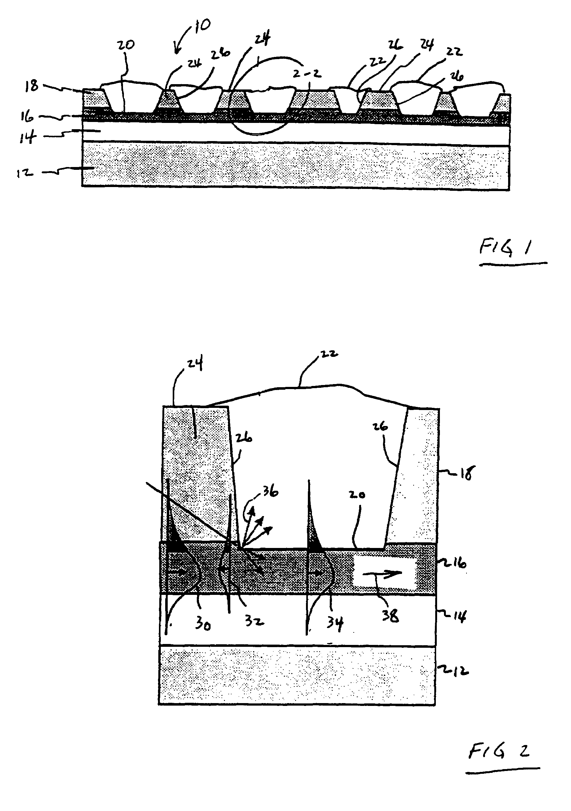
[0060]A light guide 10 according to the invention is depicted in FIGS. 1 and 2 and includes a carrier 12, such as a silicon wafer, a first inclusion, buffer or substrate layer 14, a light-transmitting or core layer 16 and a second inclusion or cladding layer 18. Parameter sensitive segments are formed in the cladding layer 18 by creating recesses 20 which may extend into the co...


PUM


Abstract

In an integrated optical lightguide device including a light-transmitting core layer, an inclusion or buffer layer, and an active or cladding layer. The cladding layer is divided into segments. Groups of different segments exhibit different refractive indices, light intensity profiles or different degrees of sensitivity which have been effected by different methods. Thus, repeated adjustable or controllable transmission has resulted in an extremely sensitive waveguide system for a sensor, a modulator, or a spectrophotometer.

Description

CROSS REFERENCE TO RELATED APPLICATIONS[0001]This application claims priority and is a continuation of International Application No. PCT / NL99 / 00222, filed Apr. 16, 1999, which claims priority of Netherlands Patent Application No. 1008934, filed Apr. 20, 1998.STATEMENT REGARDING FEDERALLY SPONSORED RESEARCH[0002]Not applicable.BACKGROUND OF THE INVENTION[0003]1. Field of the Invention[0004]The invention relates to integrated optical lightguide devices and more particularly to optical waveguide sensors, modulators and spectrophotometers.[0005]2. Description of the Related Art[0006]Integrated optical sensors are known from an article entitled “Fabrication and Packaging of Integrated Chemico-Optical Sensors” by R. G. Heideman et al., published in Sensors and Actuators, volume B 35–36, 1996, pp. 234–240. Besides sensors and actuators in a general sense, the article describes in particular a Mach-Zehnder interferometer including a deposited film, which is sensitive to air humidity. The ar...

Claims


Application Information

Patent Timeline
IPC IPC(8): G01N21/77G02F1/01G02F1/035G02B6/10
CPCG01N21/7703G02B6/10G02F1/011G02F1/035
Inventor HEIDEMAN, RENE GERRITLAMBECK, PAUL VINCENTVELDHUIS, GERRIT JAN
Owner UNIVERSITY OF TWENTE
Learn More