
Method and system for assembling and utilizing components in component object systems

a technology of component object systems and components, applied in the field of object-based computer systems and applications, can solve the problems of reducing the application development cycle time, affecting the development of new applications built of such components, and poorly optimizing components for reuse, so as to facilitate the many-to-many linkages

Inactive Publication Date: 2005-10-18
COMP ASSOC THINK INC
View PDF19 Cites 26 Cited by
  • Summary
  • Abstract
  • Description
  • Claims
  • Application Information

AI Technical Summary

Benefits of technology

[0035]The use of a declarative user input interface mechanism and a design engine enables a user readily to describe an intended application by means of declarative statements and automatically to generate an application design definition from those declarations, which application design definition then models the application infrastructure for managing component object interactions. This removes the need for a designer to write specific program code to link components. The use of declarative statements facilitates the automation of the application assembly process, facilitates application verification and maintenance.
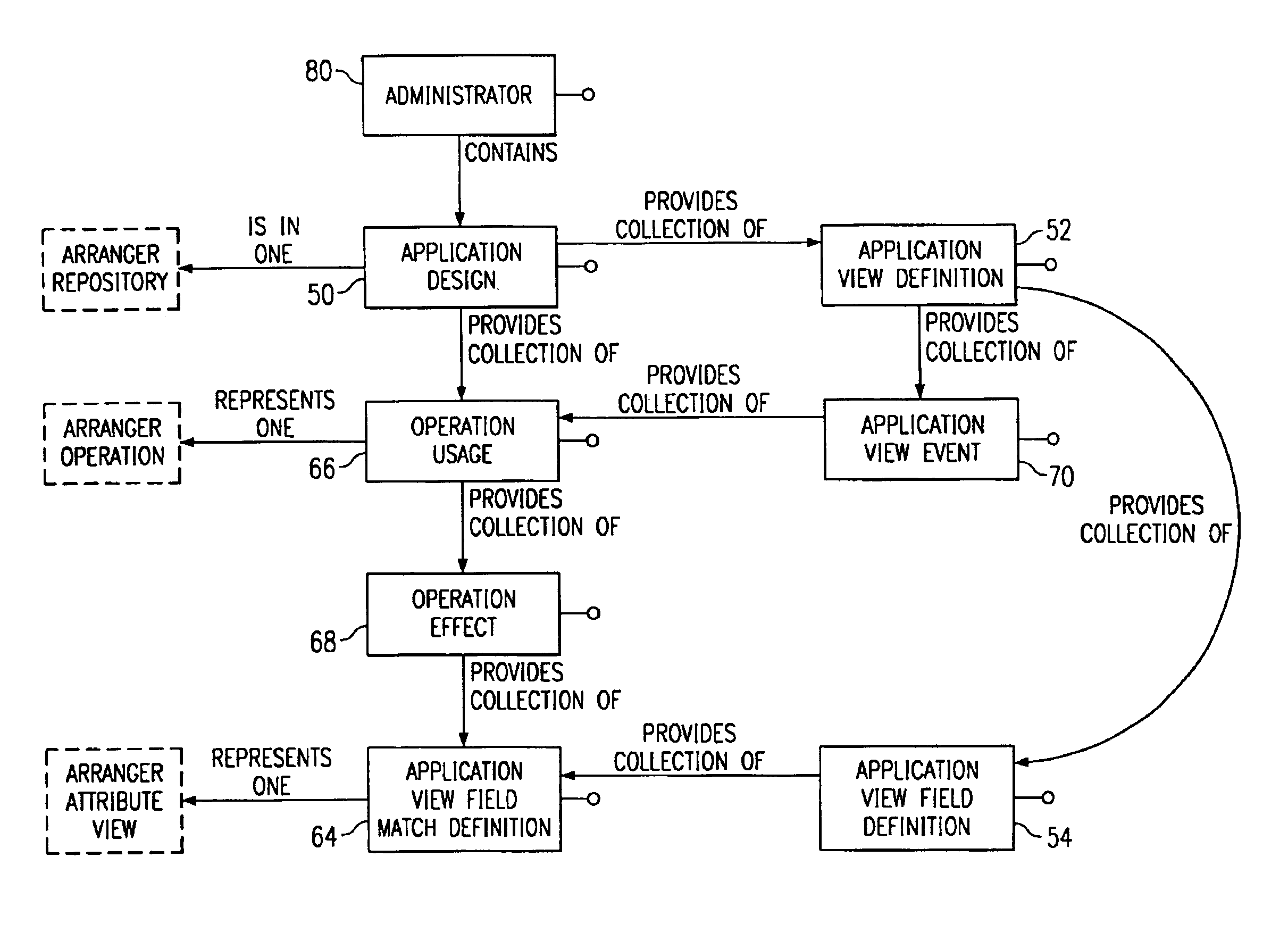
[0038]Preferably, the design engine is configured automatically to generate, in response to user input declarations, at least one operation usage definition to specify an effect a component object operation has on one or more of the application view definitions. Preferably also, the design engine is configured automatically to generate, in response to input user declarations, an event definition of an operation usage triggered by an application view definition event. More preferably, the design engine is configured automatically to generate, in response to input user declarations, a match between the application view field definition and a parameter of an associated component object operation. These mechanisms facilitate the many-to-many linkages which are needed between objects to control information flow between those objects.

Problems solved by technology

The use of proprietary protocols for messages exchanged between components and the lack of standards for describing the format and meaning of arguments passed between the components typically meant that components were poorly optimised for reuse.
The result of the poor optimisation for reuse is that the creation of new applications built of such components takes considerable time due to the necessity to create the “glue” for connecting those components.
There is considerable pressure on application developers to reduce the application development cycle time from the identification of needs to the delivery of a solution.
However, the process of assembling components into end applications remains a largely manual process.
However, to a client which requires access to a component object, the internal implementation is of little interest.
It will be appreciated from the above that the development of new applications, even using components which are ready for assembly, is a complex task requiring significant software development times by skilled engineers.

Method used


Image

  • Method and system for assembling and utilizing components in component object systems
  • Method and system for assembling and utilizing components in component object systems
  • Method and system for assembling and utilizing components in component object systems

Examples


Embodiment Construction

[0110]Embodiments of the invention as described hereinafter provide methods and systems for declaratively specifying relationships between parameters of different operations of the same or different objects, the organisation of an intermediate representation of the parameters of operations for the purpose of user interface display in an application and the effects operations have on related information, and how operations are triggered in response to certain user interface events. These characteristics are defined by means of structure termed described herein as an Application View Definition. An individual instance (in the object sense) of an Application Definition (note “instance” loosely means a copy based on a template) is referred to as an Application Instance or Application View. These terms are also used interchangeably herein. FIG. 6 is a schematic illustration of the interaction of operations and a user interface by means of an Application View 32. The term “Data Region”, w...


PUM


Abstract

A design tool for assembling component objects to form an object-based computer system application includes a declarative user input interface mechanism and a design engine. The declarative user input interface mechanism provides an input structure for the input of user declarations specifying operative interactions between component objects. The design engine automatically generates, in response to input user declarations, an application design definition modeling an application infrastructure for managing component object interactions. The design engine automatically generates, in response to input user declarations, a match between an application view field definition and a parameter of an associated component object operations. A runtime tool includes an application engine which is responsive to an application design definition and is operative at runtime automatically to create application view instances from respective application view definitions for managing runtime component object interactions for the applications.

Description

CROSS REFERENCE TO RELATED APPLICATION[0001]This application is a continuation of U.S. application Ser. No. 08 / 845,583, filed Apr. 25, 1997 now U.S. Pat. No. 6,230,309 and entitled “Object-Based Computer Systems”.FIELD OF THE INVENTION[0002]This application relates to object-based computer systems and applications, and in particular to the automatic generation and management of object-based computer system applications.BACKGROUND OF THE INVENTIONDescription of the Prior Art[0003]Object-based computing systems, in particular distributed object computing systems, are increasingly being adopted as an effective means of enabling business information systems to respond more rapidly to changes in business needs. This is achieved today by making available programs and sub-programs as components in an object-based computing system, and manually configuring those components into applications.[0004]Increasingly powerful desktop computers can provide graphical human-computer interfaces for acc...

Claims


Application Information

Patent Timeline
IPC IPC(8): B63B21/00B63B21/50E21B19/00B63B27/34G06F9/44
CPCG06F8/36
Inventor TURNER, STEPHEN J.HOGAN, PATRICK M.GIBSON, WILLIAM E.
Owner COMP ASSOC THINK INC
Learn More