Immune modulation device for use in animals

a technology of immune modulation and device, which is applied in the field of immunomodulation device for use in animals, can solve the problems of affecting the diffusion of soluble molecules out of the device, and achieve the effects of enhancing immune response, facilitating miniaturization of the device, and reducing irritation

Inactive Publication Date: 2005-10-25
ORTHO MCNEIL PHARM INC
View PDF58 Cites 32 Cited by
  • Summary
  • Abstract
  • Description
  • Claims
  • Application Information

AI Technical Summary

Benefits of technology

[0010]The present invention is directed to an implantable immune modulation device that is suitable for use in modulating an immune response in mammals, comprising an impermeable shell having a plurality of pores and said impermeable biocompatible shell having an interior lumen, a biocompatible fibrous scaffolding being disposed within said interior lumen. The fibrous scaffolding is loaded with single or multiple antigens and optionally one or more biologically active compounds such as cytokines (e.g. lymphokines, chemokines etc.), non-cytokine leukocyte chemotactic agents, attachment factors, genes, peptides, proteins, nucleotides, carbohydrates, or cells depending on the application. The shell of the device preferably is made from a polymer whose glass transition temperature is below physiologic temperature so that the device will minimize irritation when implanted in soft tissues. The shell allows cell ingress but hinders diffusion of soluble molecules out of the device. This helps to concentrate cytokines (e.g. lymphokine and chemokines) secreted by cells which have entered the device in response to loaded antigens and other cells which are present in the device. This local concentration of cells and cytokines significantly enhances the immune response relative to implantation of antigens with standard adjuvants. The fibrous scaffolding provides a scaffold for cells to reside on, process the antigens and interact.
[0011]Additional benefits of the fibrous scaffolding disclosed in this invention include ease of miniaturization of a device to diameters of less than 1 mm, the possibility of rapid insertion into small diameter tubing or even the ability to have tubing continuously extruded around the matrix.

Problems solved by technology

The shell allows cell ingress but hinders diffusion of soluble molecules out of the device.

Method used


Image

  • Immune modulation device for use in animals
  • Immune modulation device for use in animals
  • Immune modulation device for use in animals

Examples


example 1

Textured Fibrous Filling

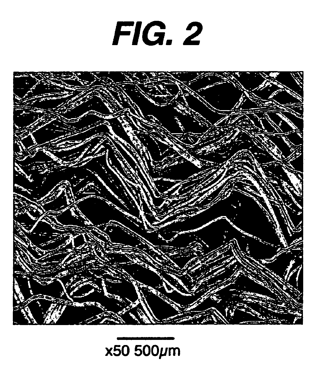
[0049]Fiber texturing was performed using a Techtex® HDC10 texturizer (Techniservice, 738 West Cypress Street, Kennett Square, Pa. 19348-0817). Nine spools of 56 denier natural 90 / 10 glycolide-co-lactide (IV of about 1.1 deciliters per gram (dl / g) as measured in a 0.1 g / dl solution of hexafluoroisopropanol at 25° C. The filaments had been drawn about 5× (original length compared to final length). The filaments were placed on the creel and combined into a single 504 denier tow by running the drawn yarns together through a common eyelet. The individual yarn filament diameters were between 12-20 μm. A pretension of 5-7 grams was used for each yarn by passing them through the gate tensioner. The large yarn tow was then passed over a heated godet with the separator roller (15 wraps) with the heated godet being set to a temperature of 130° C. This yarn tow was then fed into the stuffer box by two crimper rolls. The clearance between the stuffer box and rollers was ...

example 2

Membrane Formation

[0050]Membranes were formed from both poly(para-dioxanone) (PDO) and a copolymer of 35 / 65 epsilon-caprolactone / glycolide (CAP / GLY). The inherent viscosity (dl / g) of the PDO and CAP / GLY, as measured in a 0.1 g / dl solution of hexafluoroisopropanol (HFIP) 25° C., were 1.80 and 1.30, respectively. All membranes were formed by extrusion using a ¾-inch Brabender single-screw extruder (C.W. Brabender® Instruments, Inc., So. Hackensack, N.J.) under flowing nitrogen. Membranes with several inner and outer dimensions were formed. Extrusion conditions for the extruded membranes are shown in Table 1. Immediately following exit from the die, all membranes were run through a 12-foot cooling trough filled with chilled water at a temperature of 5-10° C. For the CAP / GLY membranes, short segments (˜2-3 ft.) were cut and hung from one end at room temperature to allow solidification and crystallization of the polymer.

[0051]

TABLE 1Extrusion conditionsDie sizeScrewTake-Die × tipTzone1Tz...

example 3

VLN Construct Formation

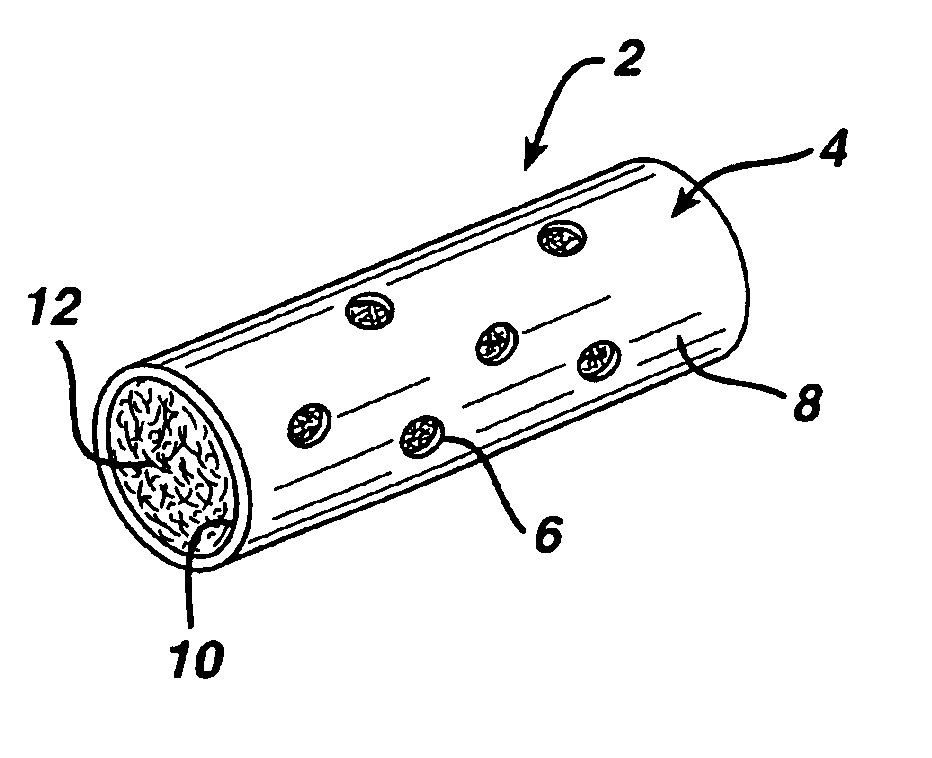
[0054]The textured fiber filling from Example 1 was placed inside the membranes discussed in Example 2 as follows. Textured fiber was attached to a small needle or thin filament of wire and pulled through the membrane. The fiber was cut to the length of the membrane. Available porosity was calculated from the volume of the inner lumen of the membrane, weight of textured yarn placed inside of the membrane, and the density of the fibers used. Table 3 shows several of the construct geometries and resultant porosities.

[0055]

TABLE 3Absorbable VLN constructs containing textured fiber.MembraneOD / ID / lengthHole diameter#Fiber weight˜PercentComposition(mm / mm / mm)(μm)holes(mg)porositySample #CAP / GLY2.0 / 1.5 / 25300201280%1CAP / GLY2.0 / 1.5 / 20300161080%2CAP / GLY2.0 / 1.5 / 20300121080%3CAP / GLY2.0 / 1.5 / 2030081080%4CAP / GLY2.0 / 1.5 / 2030041080%5CAP / GLY2.0 / 1.5 / 20not applicable01080%6CAP / GLY2.0 / 1.5 / 25300161083%7CAP / GLY2.0 / 1.5 / 25300161575%8CAP / GLY2.0 / 1.5 / 2030020883%9CAP / GLY2.0 / 1.5 / 20300201275...


PUM

PropertyMeasurementUnit
porosityaaaaaaaaaa
diameteraaaaaaaaaa
outer diameteraaaaaaaaaa

Abstract

The present invention is directed to an implantable immune modulation device that is useful for modulating an immune response in mammals, comprising a plurality of fibers, within a porous shell. The fiber filling is loaded with single or multiple antigens, and optionally one or more biologically active compounds such as cytokines (e.g. lymphokines, chemokines etc.), attachment factors, genes, peptides, proteins, nucleotides, carbohydrates or cells depending on the application.

Description

[0001]This application claims benefit of provisional patent application No. 60 / 290,542 filed May 11, 2001, which is hereby incorporated by reference herein.FIELD OF THE INVENTION[0002]The present invention relates to an implantable device and method for modulating the immune response to antigens in mammals. More specifically the present invention provides a porous, implantable device containing a fibrous support and at least one antigen. This device may be used to modulate the immune system to provide a robust response against an antigen, or to down regulate an existing response.BACKGROUND OF THE INVENTION[0003]Induction of an immune response to an antigen and the magnitude of that response depend upon a complex interplay among the antigen, various types of immune cells, and co-stimulatory molecules including cytokines. The timing and extent of exposure of the immune cells to the antigen and the co-stimulatory milieu further modulate the immune response. Within the body, these vario...

Claims


Application Information

Patent Timeline
Patent Type & Authority Patents(United States)
IPC IPC(8): A61K9/00A61K9/22A61K35/14A61K39/00A61K47/34A61P37/02A61P37/04C12N5/07C12N5/077C12N5/078
CPCA61K9/0024A61K9/0092A61K2039/515A61P37/00A61P37/02A61P37/04Y02A50/30A61K9/00
Inventor TENHUISEN, KEVOR S.ROSENBLATT, JOELKOYFMAN, ILYA S.
Owner ORTHO MCNEIL PHARM INC
Why Eureka
Try Eureka