Apparatus and method for measuring weight of an occupying item of a seat

a technology for occupying items and measuring equipment, which is applied in the direction of vehicle seats, weighing equipment for materials with special properties/forms, electric devices, etc., can solve the problems of occupants being seriously injured or killed by airbag deployment, children sitting in such seats being seriously injured or killed, etc., to improve the performance of airbags and reduce occupant injuries

Inactive Publication Date: 2005-10-25
AUTOMOTIVE TECH INT
View PDF83 Cites 53 Cited by
  • Summary
  • Abstract
  • Description
  • Claims
  • Application Information

AI Technical Summary

Benefits of technology

[0059]14. to adjust the flow of gas into and/or out of the airbag based on the morphology and

Problems solved by technology
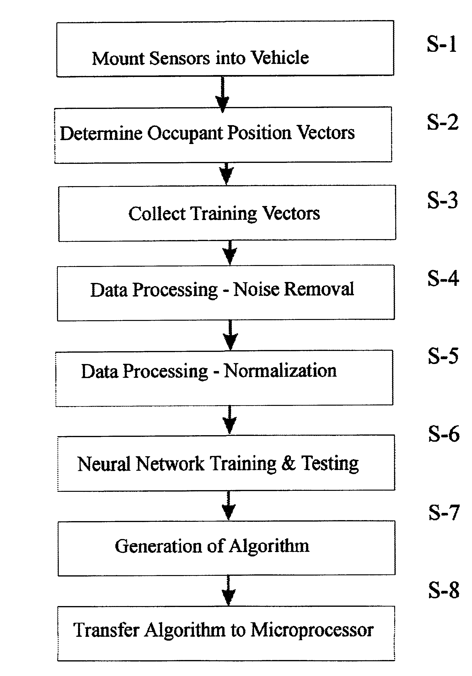
However, depending on the seated state of an occupant, there are cases where his or her life cannot be saved even by present airbag systems.
For example, when a passenger is seated on the front passenger seat in a position other than a forward facing, normal state, e.g., when the passenger is out of position and near the deployment door of the airbag, there will be cases when the occupant will be seriously injured or even killed by the deployment of the airbag.
Also, sometimes a child seat is placed on the passenger seat in a rear facing position and there are cases where a child sitting in such a seat has been seriously injured or killed by the deployment of the airbag.
Furthermore, in the case of a vacant seat, there is no need to deploy an airbag, and in such a case, deploying the airbag is undesirable due to a high replacement cost and possible release of toxic gases into the passenger compartment.
Nevertheless, most airbag systems will deploy the airbag in a vehicle crash even if the seat is unoccupied.
Also, it is sometimes difficult to discriminate the wave pattern of a normally seated child with the seat in a rear facing position from an empty seat with the seat in a more forward position.
Similar confusing situations can occur also for capacitive, electric field and optical occupant sensing systems.
One specific reason is the poor design of most seat adjustment systems particularly the so-called “4-way-seat”.
Such a seat adjustment system causes co

Method used


Image

  • Apparatus and method for measuring weight of an occupying item of a seat
  • Apparatus and method for measuring weight of an occupying item of a seat
  • Apparatus and method for measuring weight of an occupying item of a seat

Examples


Embodiment Construction

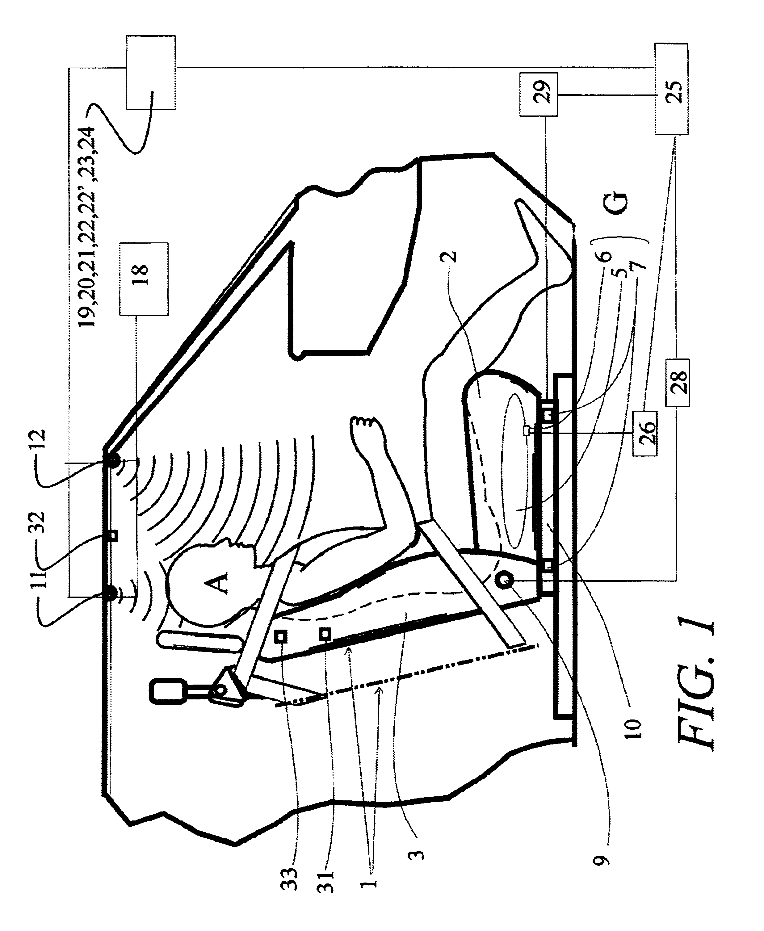
[0118]Referring to the accompanying drawings wherein like reference numbers designate the same or similar elements, FIG. 1 shows a passenger seat 1 to which an adjustment apparatus including a seated-state detecting unit according to the present invention may be applied. The seat 1 includes a horizontally situated bottom seat portion 2 and a vertically oriented back portion 3. The seat portion 2 is provided with one or more weight sensors 6 and 7 that determine the weight of the object occupying the seat. The coupled portion between the seated portion 2 and the back portion 3 is provided with a reclining angle detecting sensor 9, which detects the tilted angle of the back portion 3 relative to the seat portion 2. The seat portion 2 is provided with a seat track position-detecting sensor 10. The seat track position detecting sensor 10 fulfills a role of detecting the quantity of movement of the seat 1 which is moved from a back reference position, indicated by the dotted chain line. ...


PUM


Abstract

Arrangement and method for determining weight of an occupying item in a seat including one or more weight sensors arranged to obtain a measurement of the force applied to the seat, a forcing function determination arrangement for measuring a forcing function of the seat and a processor coupled to the weight sensor(s) and forcing function determination arrangement for receiving the measurement of the force applied to the weight sensor(s) and the measurement of the forcing function from the forcing function measurement system and determining the weight of the occupying item based thereon. The forcing function determination arrangement may include an accelerometer and measures effects on the seat caused by load of a seatbelt associated with the seat and/or effects on the seat of road roughness, steering maneuvers, and a vehicle suspension system.

Description

CROSS REFERENCE TO RELATED APPLICATIONS[0001]This application is a continuation-in-part of:[0002]1) U.S. patent application Ser. No. 09 / 500,346 filed Feb. 8, 2000 which in turn is a continuation-in-part of U.S. patent application Ser. No. 09 / 128,490, filed Aug. 4, 1998, now U.S. Pat. No. 6,078,854, which in turn is a continuation-in-part of both U.S. patent application Ser. No. 08 / 474,783 filed Jun. 7, 1995, now U.S. Pat. No. 5,822,707, and U.S. patent application Ser. No. 08 / 970,822 filed Nov. 14, 1997, now U.S. Pat. No. 6,081,757;[0003]2) U.S. patent application Ser. No. 09 / 849,558 filed May 4, 2001 now U.S. Pat. No. 6,653,577 which in turn is a continuation-in-part of U.S. patent application Ser. No. 09 / 193,209 filed Nov. 17, 1998, now U.S. Pat. No. 6,242,701, which in turn is a continuation-in-part of U.S. patent application Ser. No. 09 / 128,490 filed Aug. 4, 1998, now U.S. Pat. No. 6,078,854, which in turn is a continuation-in-part of both U.S. patent application Ser. No. 08 / 474...

Claims


Application Information

Patent Timeline
IPC IPC(8): B60N2/00B60N2/26B60N2/015B60N2/02B60N2/005B60N2/06B60N2/48B60R21/01B60N2/66B60N2/68B60N2/64B60N2/28G01G19/414G01G19/40G01S15/88G01S15/00G01S15/87B60R21/20B60R21/26B60R22/18B60R22/28B60R22/46B60R22/20G01S15/06B60R21/015B60R21/203B60R21/276
CPCB60N2/002B60N2/0232B60N2/0244B60N2/0248B60N2/0252B60N2/0276B60N2/067B60N2/28B60N2/2806B60N2/2863B60N2/4829B60N2/4852B60N2/4885B60N2/66B60N2/68G01G19/4142G01G23/3728G01S15/87G01S15/88B60R21/01554B60R21/01536B60R21/01516B60R21/01542B60R21/01526B60N2/015B60R21/0153B60N2002/0268B60R21/203B60R22/201B60R2021/26094B60R2021/2765B60R2022/288B60R2022/4685G01S15/06B60N2002/0272B60N2/888B60N2/829B60N2/853B60N2/0272B60N2/0268B60N2/02246
Inventor BREED, DAVID S.DU VALL, WILBUR E.JOHNSON, WENDELL C.
Owner AUTOMOTIVE TECH INT
Why Eureka
Try Eureka