

Inverter controller for driving motor and air conditioner using inverter controller
a technology of inverter controller and inverter, which is applied in the direction of motor/generator/converter stopper, dynamo-electric converter control, dynamo-electric gear control, etc. it can solve the problems of increasing the size and weight of the inverter, increasing the cost, and increasing the size of the apparatus, so as to reduce the fluctuation amount of the motor current, reduce the size of the inverter, and reduce the effect of weigh
- Summary
- Abstract
- Description
- Claims
- Application Information
AI Technical Summary
Benefits of technology
Problems solved by technology
Method used
Image

Examples
embodiment 1
[0073
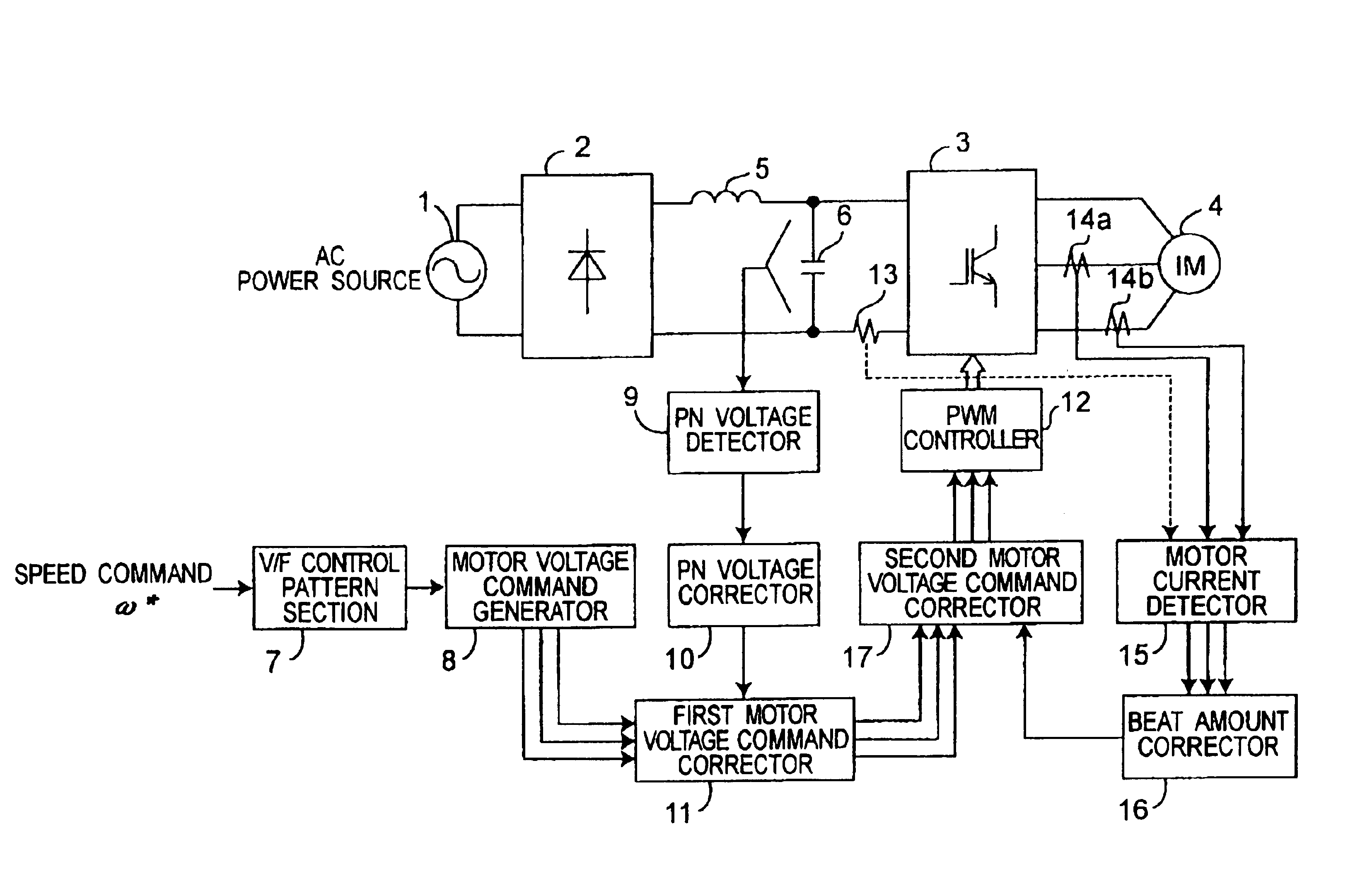
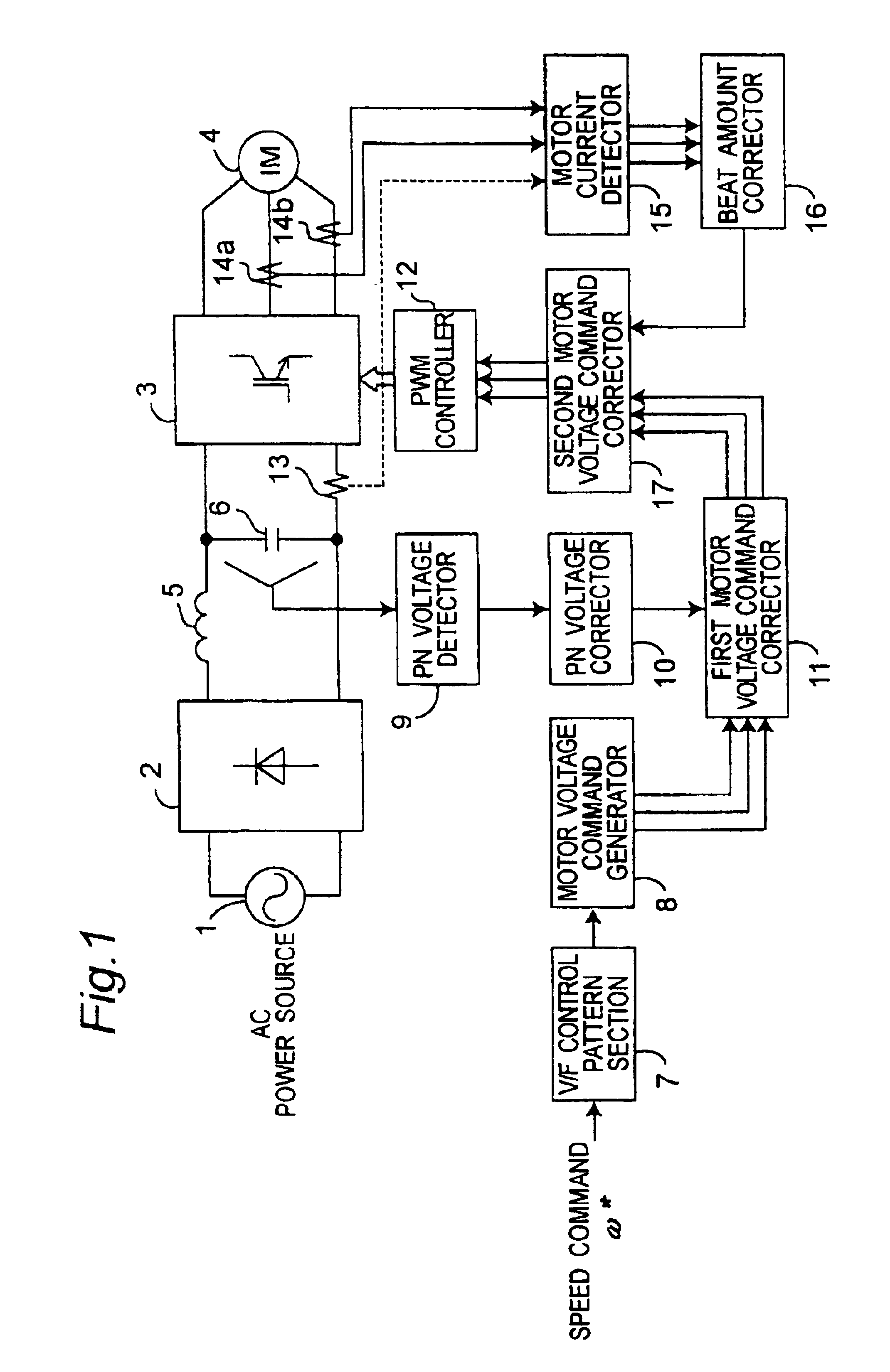
[0074]FIG. 1 shows a system constitution of an inverter controller for driving an induction motor according to a first embodiment of the present invention. Referring to FIG. 1, a main circuit of the system constitution includes an AC power supply 1, a rectifier 2 formed of a diode bridge for converting AC power to DC power, a small-capacity reactor 5, a small-capacity capacitor 6, an inverter 3 for converting the DC power to AC power, and an induction motor 4 driven by the AC power converted by the inverter 3.
[0075]Meanwhile, a system control circuit includes a V / F control pattern section 7, a motor voltage command generator 8, a PN voltage detector 9, a PN voltage corrector 10, a first motor voltage command corrector 11, a PWM controller 12, an inverter bus line current sensor 13, motor current sensors 14a and 14b, a motor current detector 15, a beat amount corrector 16, and a second motor voltage command corrector 17.
[0076]The V / F control pattern section 7 generates a V / F con...
embodiment 2
[0112
[0113]FIG. 4 shows a block construction of a beat amount corrector 16 according to a second embodiment of the present invention. The same components as in the beat amount corrector shown in FIG. 3 are allotted to the same reference signs and their descriptions are omitted here, and only different parts are described hereinafter.
[0114]Referring to FIG. 4, a motor current average calculating portion 32 calculates a motor current average value ij—mean every cycle of an inverter operation frequency f1, and a motor current average value storing portion 41 stores the motor current average values ij—mean previously provided by the motor current average calculating portion 32 in M cycles before the present calculation. In a period of calculating the motor current average value ij—mean, the motor current average value ij—mean in a period of at least M-1) cycles previous to the present calculation is set as the motor current fluctuation amount Δij, and when the period of calculating the ...
embodiment 3
[0120
[0121]FIG. 5 shows a block constitution of a beat amount corrector 16 according to a third embodiment of the present invention. Referring to FIG. 5, a motor current positive / negative determining portion 51 determines a positive or negative of a motor current detection value ij. A motor current positive to negative ratio setting portion 52 sets a motor current positive to negative ratio εj based on an output value of the motor current positive / negative determining portion 51. When the motor current positive to negative ratio εj is integrated by an integrator 31, the integration number N of the motor current positive to negative ratio εj in one cycle is stored in an integration number counter 33. A motor current positive to negative ratio average calculating portion 53 calculates a motor current positive to negative ratio average value εj—mean by dividing an output value of the integrator 31 (an integration value of the motor current positive to negative ratio εj) by the integrat...
PUM
 Abstract
Description
Claims
Application Information