
Motion-free tracking solar concentrator

a solar concentrator and motion-free technology, applied in the direction of instruments, polarising elements, lighting and heating apparatuses, etc., can solve the problems of high total mass, high cost, and large number of mechanical drives, so as to improve reliability, design and construction of support structures, and resist wind vibration. , the effect of improving reliability

Active Publication Date: 2005-10-25
PENDER JOHN GEORGE
View PDF3 Cites 190 Cited by
  • Summary
  • Abstract
  • Description
  • Claims
  • Application Information

AI Technical Summary

Benefits of technology

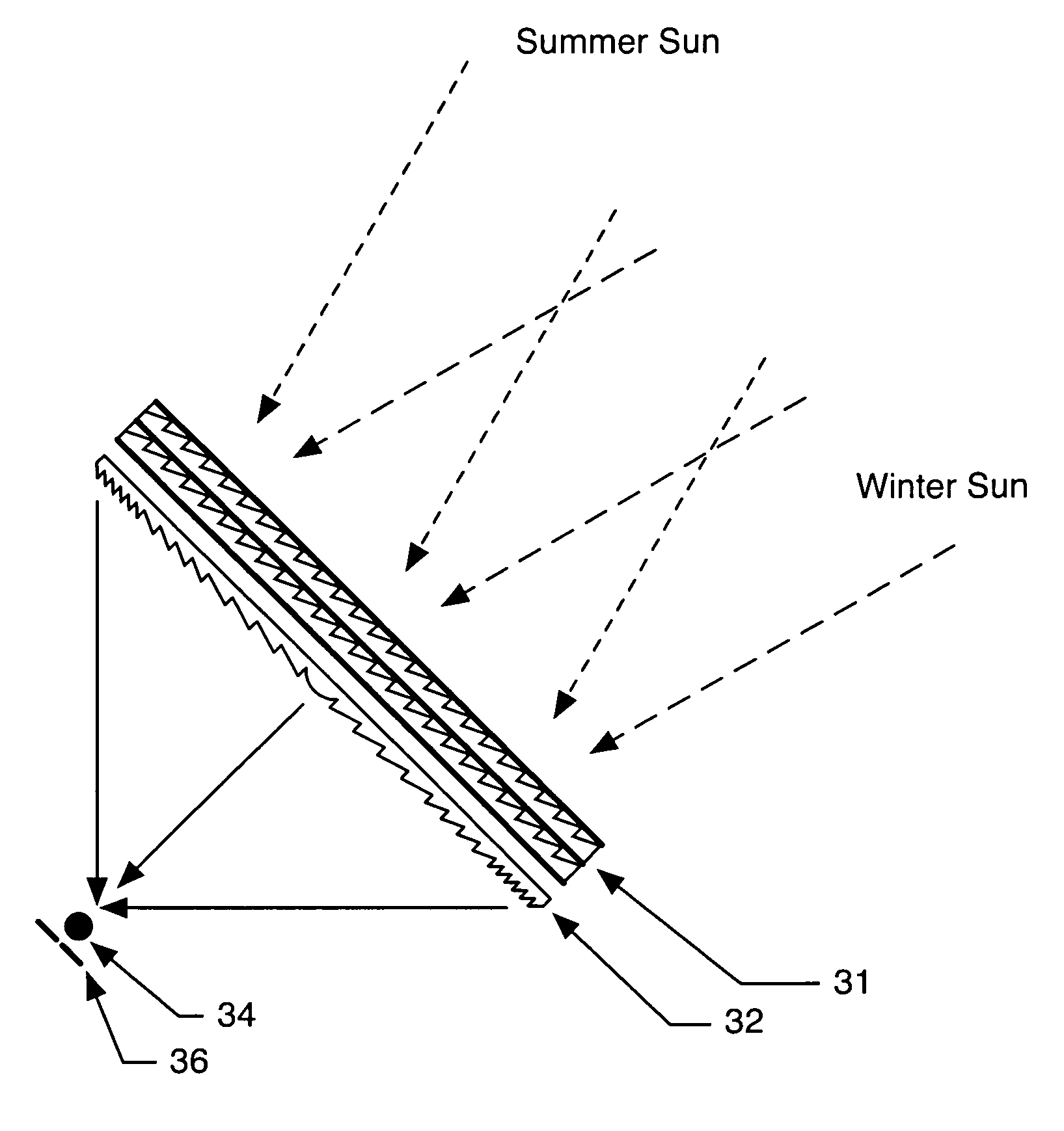
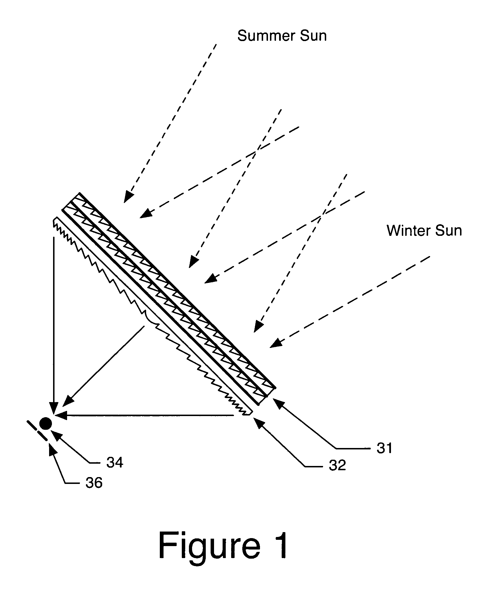
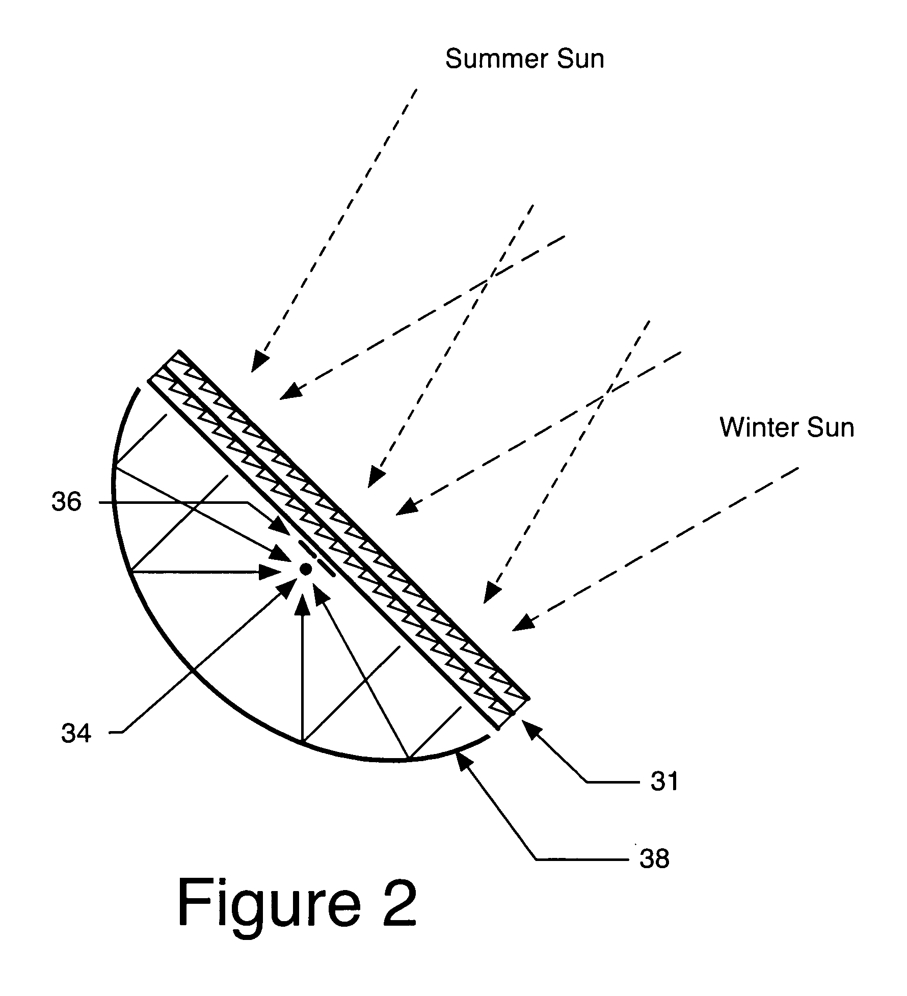
[0010]The invention is a solar collector consisting of a Fresnel lens or other optical condenser, and one or more arrays of prismatic cells made from a material whose refractive index may be varied by applying an electromagnetic field. The refractive index of the cells is varied by the applied field in such a manner as to direct sunlight at a fixed angle into the condenser which then concentrates the light to a focus. The field is adjusted as the sun moves in the sky in order to keep the position of the optical focus fixed. There are no moving parts. Since the concentrator does not need to move, the design and construction of a support structure which resists vibration from wind is easier. Elimination of a mechanical tracking mechanism improves reliability and reduces overall weight. Other objects and advantages of the present invention will become apparent from the following descriptions, taken in connection with the accompanying drawings, wherein, by way of illustration and example, an embodiment of the present invention is disclosed.

Problems solved by technology

Potential failure of the motion drive presents reliability and maintenance issues.
As the collector is made larger for higher power systems its increased mass requires more robust support and tracking infrastructure, which leads to even higher total mass.
At some point it makes sense to replace a single large collector with an array of smaller collectors, each of which has its own tracking mechanism, but the large number of mechanical drives compromises maintenance and reliability.

Method used


Image

  • Motion-free tracking solar concentrator
  • Motion-free tracking solar concentrator
  • Motion-free tracking solar concentrator

Examples


Embodiment Construction

Introduction

[0064]The collection and concentration of solar energy is a fundamental component in many heating, power generation, and daylighting applications. A first application is solar water heating. This is often accomplished by circulating water in a length of conduit, both ends of which connect to a holding tank. Solar radiation is concentrated on a section of the conduit, which gradually warms the water in the tank as the water in the conduit circulates.

[0065]A second application is the production of electric power using photovoltaic cells. Many applications involve a large-area device which collects the radiation and concentrates it onto a small photovoltaic cell which is specially designed to handle high power density. The point is to lower overall cost by reducing the area of expensive photovoltaic cells by incorporating relatively low-cost solar concentrators.

[0066]A third application is fiberoptic daylighting. This refers to the process of collecting visible radiation fr...


PUM


Abstract

An integrated solar concentrator and tracker is constructed from a beam deflector for unpolarized light in combination with a fixed optical condenser. The one-dimensional beam deflector consists of a pair of prism arrays made from a material whose refractive index can be varied by applying an electric field. Two of the one-dimensional concentrators can be arranged with their faces in contact and with their prism arrays perpendicular to construct a two-dimensional beam deflector. The intensity and distribution of an applied field modifies the refractive index of the individual prisms in order to keep direction of the deflected beam fixed as the incident beam shifts. When the beam deflector is used with the fixed concentrator the result is that the position of the focus remains fixed as the source moves.

Description

CROSS REFERENCE TO RELATED APPLICATIONS[0001]Not ApplicableSTATEMENT REGARDING FEDERALLY SPONSORED RESEARCH OR DEVELOPMENT[0002]Not ApplicableDESCRIPTION OF ATTACHED APPENDIX[0003]Not ApplicableFIELD OF THE INVENTION[0004]This invention relates generally to the field of solar power and more specifically to a machine for concentrating solar radiation.DESCRIPTION OF THE PRIOR ART[0005]A number of systems for passive, or non-tracking, concentration of solar energy in one dimension to a line-like focus have been produced in the past. Among such systems are those shown in U.S. Pat. Nos. 6,467,916, 5,537,991, 5,289,356, 4,487,961, 4,359,265, 4,230,095, 4,003,638, and 4,002,499. A common characteristic of these systems is the use of smooth reflective surfaces to reflect light from the sun onto a region to be heated, such as a fluid-filled conduit.[0006]The overall efficiency of the heating process is improved if the system incorporates a tracking mechanism to compensate for the apparent da...

Claims


Application Information

Patent Timeline
IPC IPC(8): F24J2/00G02B3/08G02B5/30G02B27/28H01L25/00F24S23/00F24S23/30F24S50/20G02B5/04G02F1/1335G02F1/29H01L31/052
CPCF24J2/06H01L31/0547F24J2/085F24J2/38G02B5/045H01L31/0543F24J2/062G02F1/29Y02E10/43Y02E10/44Y02E10/47Y02E10/52G02F1/133526F24S23/00F24S50/20F24S23/31F24S23/10
Inventor PENDER, JOHN GEORGE
Owner PENDER JOHN GEORGE
Learn More