Brushless motor and disk drive apparatus

a disk drive and motor technology, applied in the direction of motor/generator/converter stopper, dynamo-electric converter control, instruments, etc., can solve the problems of increasing cost, difficult to drive and control the motor at a low speed, and inability to detect the rotational position correctly, so as to reduce the vibration and acoustic noise of the disk remarkably, and the effect of stable and secure rotational driv

Inactive Publication Date: 2005-10-25
PANASONIC CORP
View PDF8 Cites 6 Cited by
  • Summary
  • Abstract
  • Description
  • Claims
  • Application Information

AI Technical Summary

Benefits of technology

[0092]The phase adjusting means can comprise first timing adjust means for changing a first state signal every first adjust time T1 (T1<T0 / 2) which responds with the time interval T0 of the position signal, second timing adjust means for changing a second state signal every second adjust time T2 (T2<T1 / 2) which responds with the time interval T0, and the signal producing means for producing at least one rotation activation control signal responding with the first state signal and the second state signal and for controlling the period of activation to at least one of the Q first power amplifying means and the Q second power amplifying means in response to at least one activation control signal. Hence, activation phases can be altered in accurate timing synchronized with the position signal, and it is possible to attain stable secure rotational drive.
[0093]The signal producing means can be configured to produce a slope signal responding with the second state signal, to produce Q-phase first activation control signals responding with the first state signal and the slope signal, and to control the activation to the Q first power amplifying means in response to the Q-phase first activation control signals. Furthermore, the signal producing means can also be configured to produce Q-phase second activation control signals responding with the second state signal and the slope signal, and to control the activation to the Q second power amplifying means in response to the Q-phase second activation control signals. This configuration can supply smooth drive current to the windings, and can reduce the vibration and acoustic noise of the disk remarkably.
[0094]Furthermore, the disk drive apparatus can comprise commanding means for producing a command signal responding with the rotational speed of the rotor and switching means for subjecting at least one of the Q first power amplifying means and the Q second power amplifying means to high-frequency switching operation in response to the command signal. This reduces the power losses of the power transistors and can realize a disk drive apparatus with low power consumption.

Problems solved by technology

This has caused the necessity of a substantial space for installing these position sensors and the complexity of the wiring, resulting in an increase in cost.
In the motor with no position sensor, however, the rotational position cannot be detected correctly at a low rotational speed of the motor, since the magnitudes of the back-electromotive forces become too small to detect at a low rotational speed of the motor.
So, it is difficult to drive and control the motor at a low speed.
In particular, in the case when the rotational speed is controlled by using a pulse signal which responds with the detected back-electromotive forces, a large fluctuation occurs in the rotational speed of the motor at a low speed because of the inaccurate detection of the pulse signal.
However, in the case of the motor with the single position sensor, positional information in the stop state of the rotor is insufficient, thereby starting and acceleration of the motor with the single position sensor becomes unstable.
Accordingly, the starting and acceleration of the rotor are not carried out smoothly, resulting in a starting failure.
Furthermore, in the configuration of the motor according to the specification of the U.S. Pat. No. 5,729,102, it is difficult to estimate the rotational electrical angle with a fine step resolution.
In particular, the error in the estimated electrical angle becomes larger at a higher rotational speed.
Accordingly, precise rotation control of the motor has been difficult.

Method used


Image

  • Brushless motor and disk drive apparatus
  • Brushless motor and disk drive apparatus
  • Brushless motor and disk drive apparatus

Examples


embodiment 1

[0180]The second timing adjust part 103 comprises a second cyclic count circuit 231, a second state circuit 232 and a second adjust circuit 233. The second cyclic count circuit 231 receives the measured data signal Da in response to the measure operation signal Dp, and counts down the pulses of the fourth clock signal Ck4 of the clock circuit 130. When the internal data of the second cyclic count circuit 231 reaches zero, a second timing signal Fb is generated. The second cyclic count circuit 231 receives the measured data signal Da again in response to the generation of the second timing signal Fb and counts down again. As a result, after the generation of the measure operation signal Dp, the second cyclic count circuit 231 outputs the second timing signal Fb every second adjust time T2 which responds to the measured data signal Da. The second adjust time T2 is substantially proportional to the time interval T0 of the position pulse signal Dt. The second adjust time T2 is sufficien...

embodiment 2

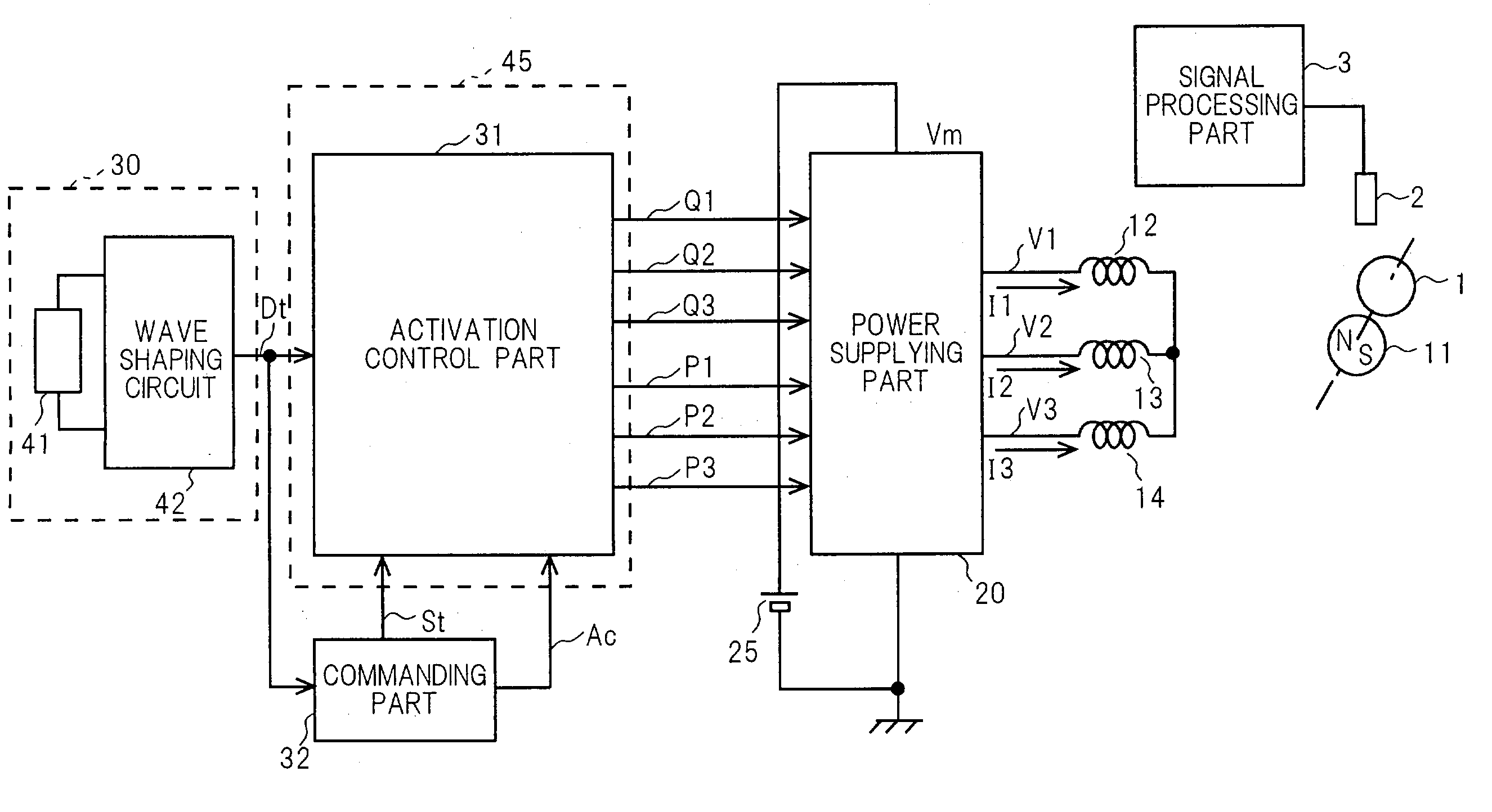
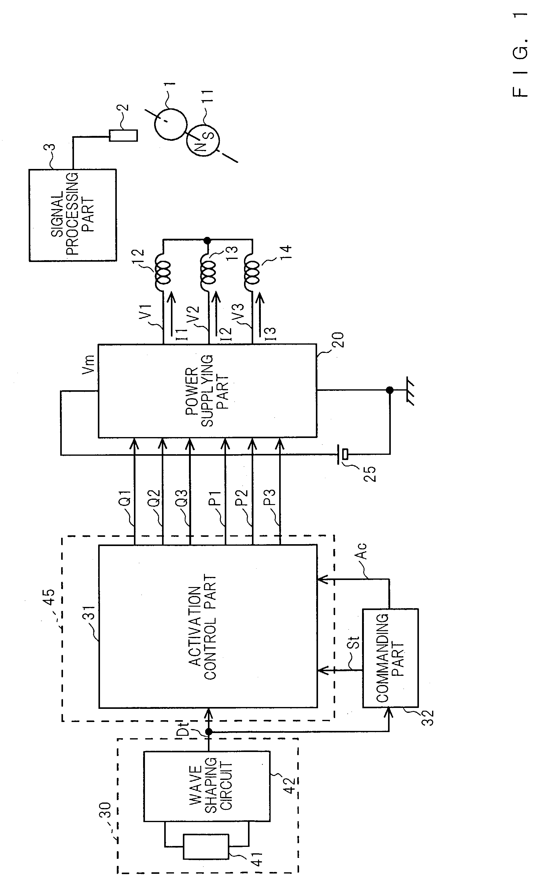
[0246]In the case when the switch part 701 selects the current control signal Af supplied from the current control part 700, the amplitudes of the first activation control signals P1, P2 and P3 and the second activation control signals Q1, Q2 and Q3 change in response to the current control signal Af. In Embodiment 2, the current detecting part 33, the current control part 700, the activation control part 31 and the power supplying part 20 form a current control loop. The composed supply current Ig supplied to the three-phase windings 12, 13 and 14 is controlled accurately in response to the command signal Ac. Furthermore, the three-phase first activation control signals P1, P2 and P3 and the three-phase second activation control signals Q1, Q2 and Q3 become smooth current signals which have substantially slope portions responding with the slope signal by using the first adjust signal and the second adjust signal which respond with the position pulse signal Dt. As a result, the puls...

embodiment 3

[0263]In Embodiment 3, as described above, the power transistors for supplying the drive currents to the windings 12, 13 and 14 perform ON-OFF high-frequency switching operation, whereby the power losses of the power transistors are reduced remarkably. In other words, the first power transistors of the first power amplifying parts 351, 352 and 353 perform ON-OFF high-frequency switching operation. The second power transistors of the second power amplifying parts 355, 356 and 357 also perform ON-OFF high-frequency switching operation. This remarkably reduces the power losses of the first and second power transistors. Hence, the heat generation of the motor and the disk drive apparatus can be reduced remarkably. As a result, starting and acceleration can be carried out by using large currents, whereby starting can be carried out securely in a short time. In addition, the disk drive apparatus can carry out recording and / or reproduction stably on a recordable disk.

[0264]In Embodiment 3,...


PUM

PropertyMeasurementUnit
electrical angleaaaaaaaaaa

Abstract

A brushless motor has first and second power transistors which form current paths to three-phase windings so as to rotate a rotor. A position detecting part produces a position signal in response to a rotation of the rotor. An activation operation block controls active operation of the first and second power transistors in response to the position signal. The activation operation block includes a starting operation part which comprises an initial phase setting part, phase changing part and a phase correcting part. The initial phase setting part sets an initial phase of drive signals to the three-phase windings in response to the level of the position signal at the timing of a start signal. The phase changing part changes sequentially the phase of the drive signals to the three-phase windings in the positive direction in response to time. The phase correcting part corrects the phase of the drive signals to the three-phase windings in response to the occurrence of the rising and falling edges of the position signal. Therefore, the brushless motor with reduced position sensor can stably start the rotation of the rotor by using one position signal of one position sensor.

Description

FIELD OF THE INVENTION[0001]The present invention relates to a brushless motor and a disk drive apparatus including the brushless motor.BACKGROUND OF THE INVENTION[0002]In recent years, a motor wherein current paths are electronically altered by plural transistors has been widely used as a drive motor in office automation equipment and audio-visual equipment. A disk drive apparatus, such as an optical disc drive apparatus (DVD, CD, and the like) and a magnetic disk drive apparatus (HDD, FDD, and the like), includes such a motor. As an example of such a conventional motor, a motor wherein current paths are altered by PNP-type and NPN-type bipolar power transistors is disclosed on lines 16 to 31 in the first column and FIG. 34 in the specification of the U.S. Pat. No. 5,982,118.[0003]FIG. 35 shows a prior art motor, and the operation of the prior art motor is described below. A rotor 2011 has a field part formed by a permanent magnet. In a position detector 2041, three position sensor...

Claims


Application Information

Patent Timeline
Patent Type & Authority Patents(United States)
IPC IPC(8): H02P6/00H02P6/22
CPCH02P6/22H02P2209/07
Inventor GOTOU, MAKOTONAGASE, HISANORITAGOME, MASAKI
Owner PANASONIC CORP
Why Eureka
Try Eureka