Bidirectional multiplexer and demultiplexer based on a single echelle waveguide grating

a multi-directional and echelle technology, applied in the field of optical communication, can solve the problems of less favorable integration devices such as awg and echelle grating for such applications, prone to errors in multiplexing optical signals, and low device mismatching error tolerance in dense wdm communication systems

Inactive Publication Date: 2005-10-25
ENABLENCE
View PDF12 Cites 8 Cited by
  • Summary
  • Abstract
  • Description
  • Claims
  • Application Information

AI Technical Summary

Problems solved by technology

Thus integrated devices such as AWG and echelle grating are less favorable for such applications due to the small channel count that they require.
Unfortunately, using two different devices for each of the individual steps of demultiplexing and of multiplexing optical signals are prone to errors associated with the mismatched channel wavelengths.
Such dense WDM communications systems have much lower device mismatching error tolerance due to the decrease in channel spacing.
It will be apparent to one of skil

Method used


Image

  • Bidirectional multiplexer and demultiplexer based on a single echelle waveguide grating
  • Bidirectional multiplexer and demultiplexer based on a single echelle waveguide grating
  • Bidirectional multiplexer and demultiplexer based on a single echelle waveguide grating

Examples


second embodiment

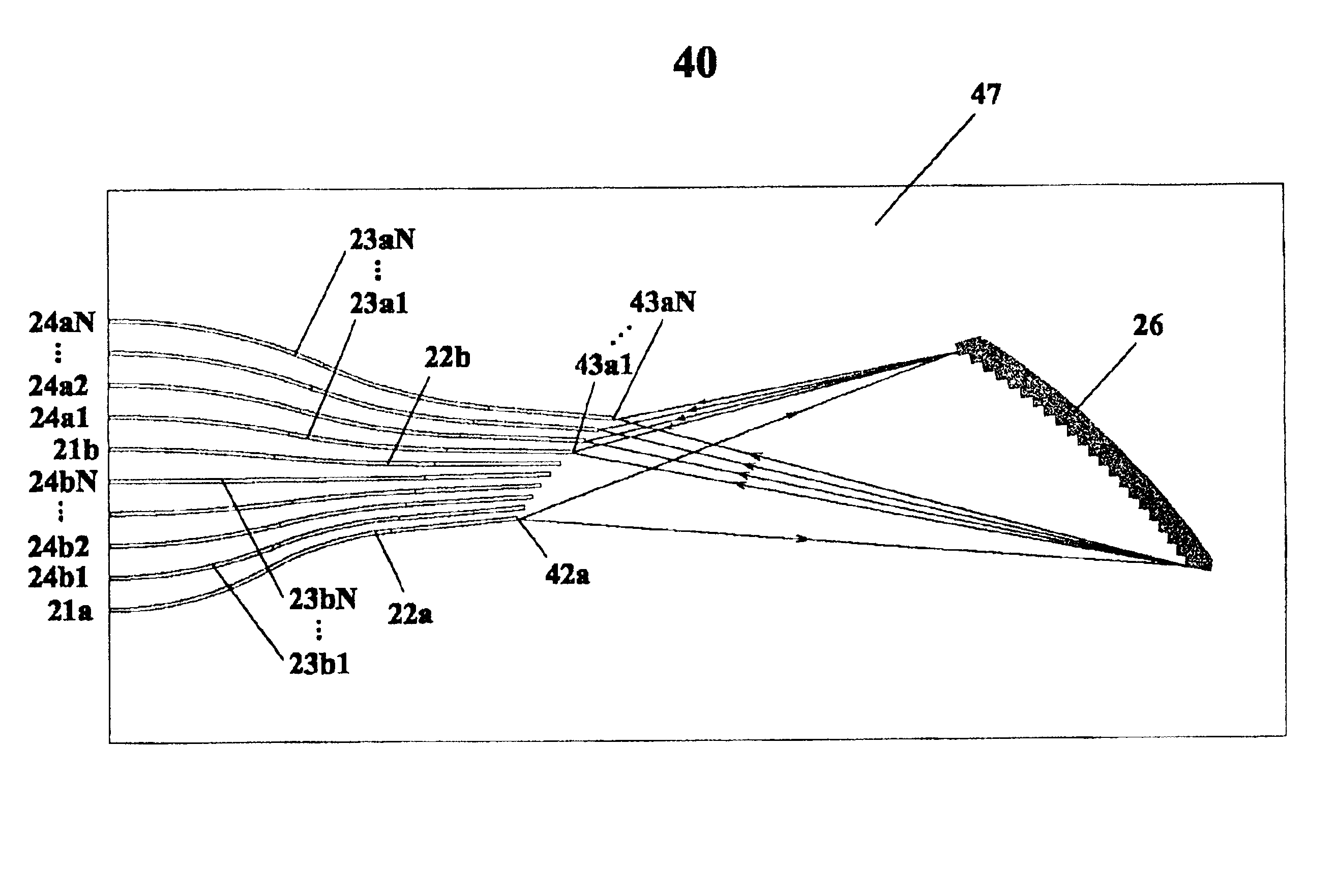
[0064]With reference to FIG. 6 an integrated multi / demultiplexer device employing a same dispersive element for demultiplexing and multiplexing a plurality of different optical signals according to the current invention is shown generally at 60.

[0065]The device comprises an input port 21a for coupling a first multiplexed optical signal containing a first plurality of wavelength channels from an optical fiber to an input waveguide 22a; a plurality of output ports 24a1 to 24aN, each for coupling a channelized signal of said first plurality of wavelength channels from a single corresponding waveguide 23a1 to 23aN to an optical fiber; a plurality of input ports 24b1 to 24bN, each for coupling a single wavelength signal of a second plurality of wavelength channels from an optical fiber to a single corresponding waveguide 23b1 to 23bN; an output port 21b for coupling a second multiplexed optical signal containing said second plurality of wavelength channels from an output waveguide 22b to...

first embodiment

[0068]It is an advantage of the embodiment that a plurality of wavelength channels are demultiplexed and multiplexed simultaneously using a same dispersive element. Thus the problems associated with mismatching performances of two optical devices are avoided. It is a further advantage of the first embodiment that the device is small compared to AWG based devices and that the input / output ports can be coupled to a single fiber array, thus reducing the packaging cost. The insertion loss of the device is minimized for both the demultiplexer and multiplexer for all channels, according to the preferred embodiment of the invention.

[0069]It is apparent to those skilled in the art that modifications and alternative embodiments can be made without departing substantially from the teachings of the invention. For example, from the first preferred embodiment of the invention, the direction of propagation of the signals can be reversed in one or both of the multiplexer and demultiplexer. The cha...


PUM


Abstract

A bidirectional multiplexer and demultiplexer based on a single waveguide grating is presented. In one embodiment of the invention, the device contains a multi/demultiplexer having an echelle grating disposed between a plurality of input channels and a plurality of output channel arrays. The input and output channels are assigned in a particular order, such that the multiplex and demultiplex functions have the same wavelength channels and such that the blaze angle of the grating facets are optimized simultaneously for both the multiplex and demultiplex function. Because the optical signals are multiplexed and demultiplexed by the same dispersive element, problems of mismatching performance introduced by using different optical components are obviated. The input/output waveguides of the dual-function device can be coupled to a single fiber array, thus reducing the packaging cost.

Description

[0001]This file claims the benefit of Provisional Application No. 60 / 257,095, filed Dec. 22, 2000.FIELD OF THE INVENTION[0002]The invention relates generally to optical communications and in particular to integrated optic grating multi / demultiplexers.DESCRIPTION OF THE PRIOR ART[0003]The information that is transmitted over most optical communications networks is typically encoded within a plurality of different wavelength channels that are multiplexed together into a signal for transmission over an optical fiber. Thus, in order to extract useful information it is necessary to demultiplex the multiplexed optical signal by separating the multiplexed signal into its component wavelength channels. Often, at least some component wavelength channels are dropped from the optical signal. Alternatively, the signals that are carried over certain wavelength channels are modified, detected or otherwise processed, for instance at a node on an optical network. Finally, a new multiplexed signal i...

Claims


Application Information

Patent Timeline
IPC IPC(8): G02B6/12G02B6/34G02B5/18
CPCG02B6/12007G02B6/12009G02B2006/12107
Inventor HE, JIAN-JUNBEROLO, ORAZIODAVIES, MICHAEL
Owner ENABLENCE
Why Eureka
Try Eureka