Soil and topography surveying

a topography and soil technology, applied in the field of soil and topography surveying and mapping, can solve the problems of soils subject to frequent waterlogging and flooding, low stability of soils, and slow surface drainage and internal drainage, so as to improve the efficiency of in-field subsurface surveying, improve sampling strategy flexibility, and improve the effect of human resources

Inactive Publication Date: 2005-10-25
TRIMBLE NAVIGATION LTD
View PDF110 Cites 35 Cited by
  • Summary
  • Abstract
  • Description
  • Claims
  • Application Information

AI Technical Summary

Benefits of technology

[0049]Various aspects of the invention can greatly improve in-field subsurface surveying efficiency over present methods. By building directly upon pre-existing subsurface and other survey data, for example, in-field testing time can be reduced. Further, such techniques offer particular advantage when test planning, reference data integration, sensor data collection and analysis are performed on-the-fly while the test platform is on site, in many cases in the course of a single day. In the United States these methods can take particular advantage of readily available USDA-NRCS Soil Surveys as part of the initial reference data for test planning. Standard computing platforms may be programmed to perform many aspects of these methods in semi-automated fashi

Problems solved by technology

Surface drainage and internal drainage are very slow, and when wet, the soils have low stability.
The soils are subject to frequent water-logging and flooding or ponding during periods of run-off.
Frequent waterlogging and potential for flooding or ponding are sever limitations for most other uses.
However, the text descriptions of the soil series are currently only available in text format that can be read and viewed by an individual, but not readily compared digitally to sample or sensor data.
It is generally understood that such rough scales are not particularly useful for high precision applications, such a

Method used


Image

  • Soil and topography surveying
  • Soil and topography surveying
  • Soil and topography surveying

Examples


Embodiment Construction

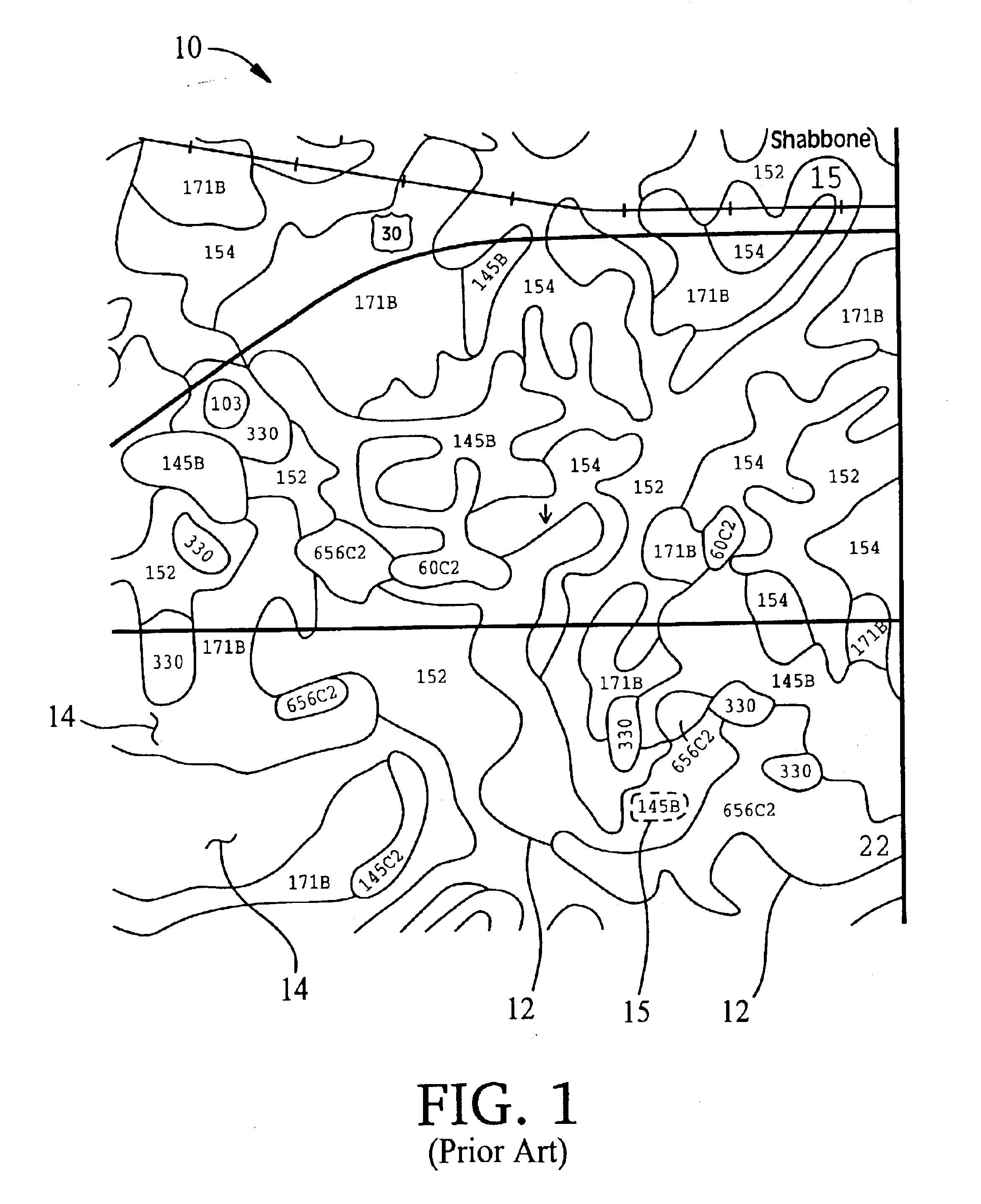
[0061]Referring first to FIG. 1, soil topology information is shown in air photo 10 overlaid with closed boundaries or polygons 12 each enclosing a geographic region 14 or “soil map unit” labeled with a number corresponding to a specific subsurface material characteristic reference profile identified in a USDA-NRCS Soil Survey as a soil series description. In this illustrated example covering approximately 1000 acres, there are several polygons 12, each of which bounds a numbered soil map unit 14. As the numeric label 15 of the soil map unit corresponds to a particular characteristic soil type and profile, many soil map units in this field have identical labels. As shown, the polygons are of irregular shape as determined by local topology and rough sampling at the time of the survey.

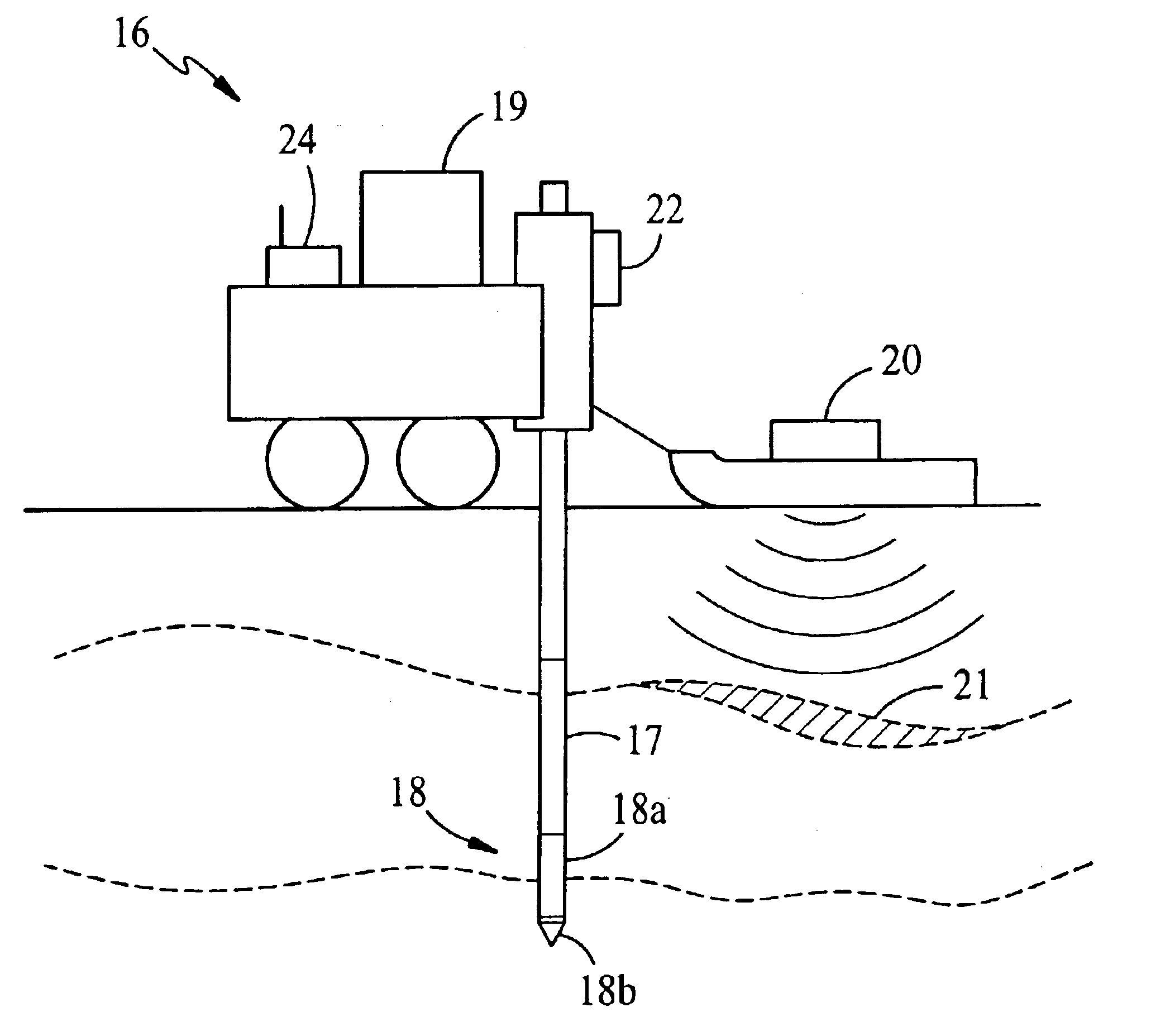
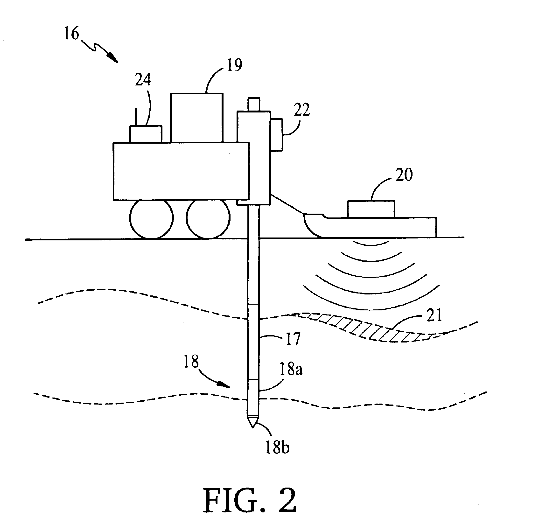
[0062]FIG. 2 illustrates a test vehicle 16 adapted to collect in-field subsurface and available data for the site. Vehicle 16 includes a push system for pushing cone penetrometer (CPT) probes 17 or other...


PUM


Abstract

Methods of characterizing subsurface conditions in a selected geographic region previously associated as a whole with a specific subsurface material characteristic reference profile such as from a USDA-NRCS soil survey. The method includes deploying a sensing tool at selected positions within the geographic region to determine a depth-referenced subsurface material characteristic such as soil type or strata, comparing the determined subsurface material characteristic to the subsurface material characteristic reference profile associated with the geographic region to determine a correlation between the subsurface material characteristic reference profile and the depth-referenced subsurface material characteristic, and then deciding whether to deploy the tool at another position, and at what optimum position to deploy the tool, by considering the correlation.

Description

[0001]This is a continuation of U.S. patent application Ser. No. 09 / 998,863, filed Nov. 1, 2001 now U.S. Pat. No. 6,597,992.FIELD OF THE INVENTION[0002]This invention relates to methods of soil and topography surveying and mapping, and more particularly to guiding the location of soil sampling and sensor testing in areas for which pre-existing survey data of various types are available.BACKGROUND OF THE INVENTION[0003]Soil information is publicly available in the United States as air photos overlaid with closed boundaries or polygons each enclosing a geographic region or “soil map unit” labeled with a number corresponding to a specific subsurface material characteristic reference profile identified in a United States Department of Agriculture—Natural Resource Conservation Service (USDA-NRCS) Soil Survey as a soil series description. Such soil surveys are presently available for over ninety percent of the geographic area of the United States, and other types of soil characterization ...

Claims


Application Information

Patent Timeline
IPC IPC(8): G01V3/38G05D11/00G06F19/00G01V11/00
CPCG01V11/00A01C21/007
Inventor ROONEY, DANIEL JAMESDUDKA, MAREKCHEYNE, MARK ANDREW
Owner TRIMBLE NAVIGATION LTD
Why Eureka
Try Eureka