
Method of inspecting a heat exchanger and computer program product for facilitating same

a heat exchanger and computer program technology, applied in the direction of mechanical roughness/irregularity measurement, digital computer details, instruments, etc., can solve the problems of difficult relocating to a tube, unable to ensure the accurate identity of an individual tube, and high human error risk, so as to achieve fast and accurate process

Active Publication Date: 2005-10-25
WESTINGHOUSE ELECTRIC CORP
View PDF14 Cites 18 Cited by
  • Summary
  • Abstract
  • Description
  • Claims
  • Application Information

AI Technical Summary

Benefits of technology

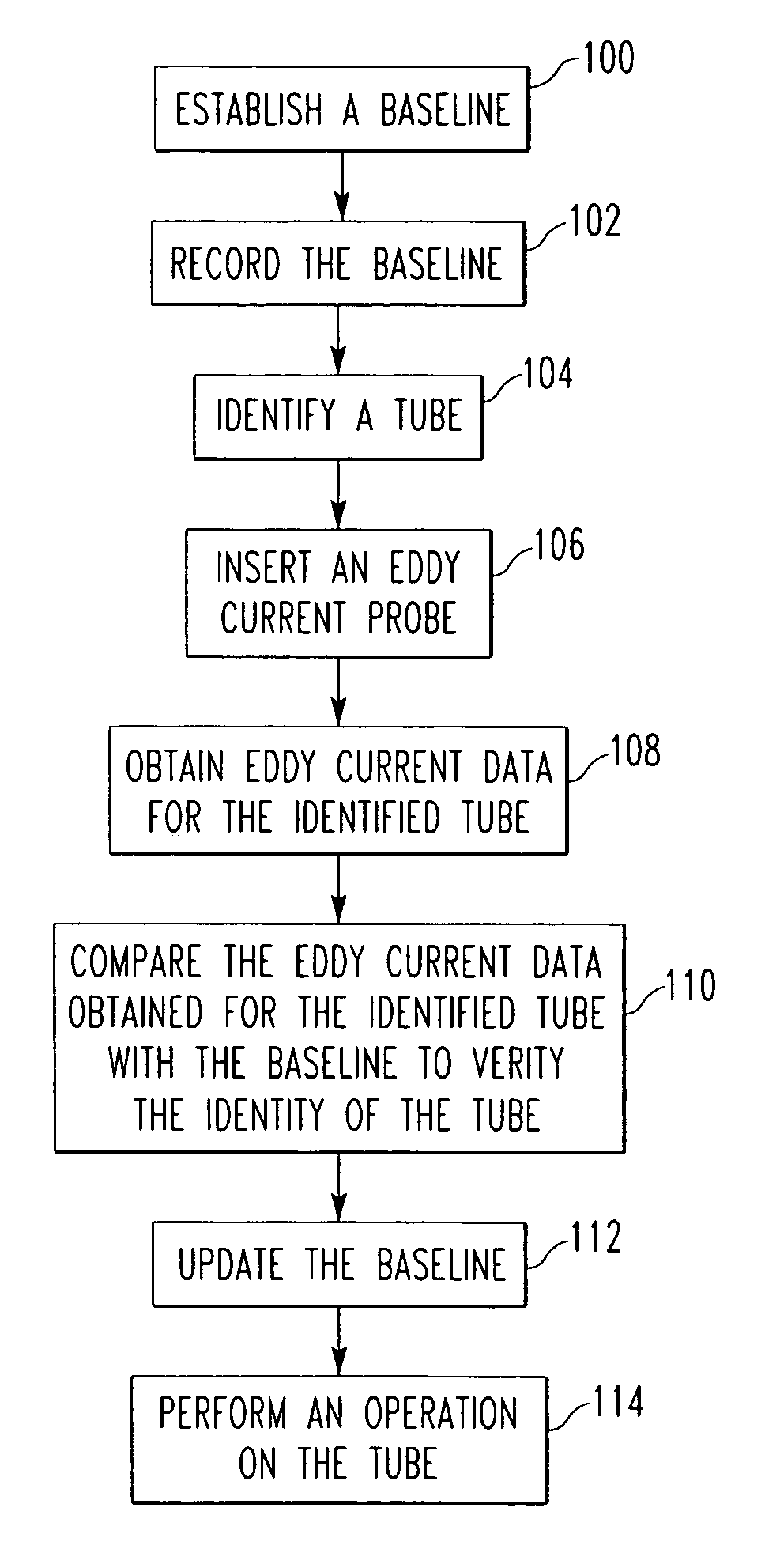
The present invention provides a fast and accurate process of identifying and verifying the identity of individual tubes in a heat exchanger, such as a steam generator for a nuclear power generation station. This is achieved by establishing a baseline for each tube of its location in the tubesheet and its unique signal pattern resulting from fixing the tube end in the tubesheet, and comparing the signal pattern data obtained for a first identified tube with the baseline data to verify its identification. The unique signal pattern may be a unique eddy current pattern resulting from fixing the tube end in the tubesheet. The method may be carried out in real-time by verifying the correct identification of the first identified tube while the eddy current probe is inserted in the tube. The computer program product includes a computer system and a computer-readable medium containing the method for inspecting a heat exchanger.

Problems solved by technology

In view of the thousands of tubes in a typical generator, this was an extremely time consuming, arduous and tedious procedure, the results of which were highly susceptible to human error.
Ensuring the accurate identity of an individual tube or relocating to a tube was also very difficult.
Moreover, it was a dangerous process, potentially exposing the technicians to an unacceptable dose of radiation.
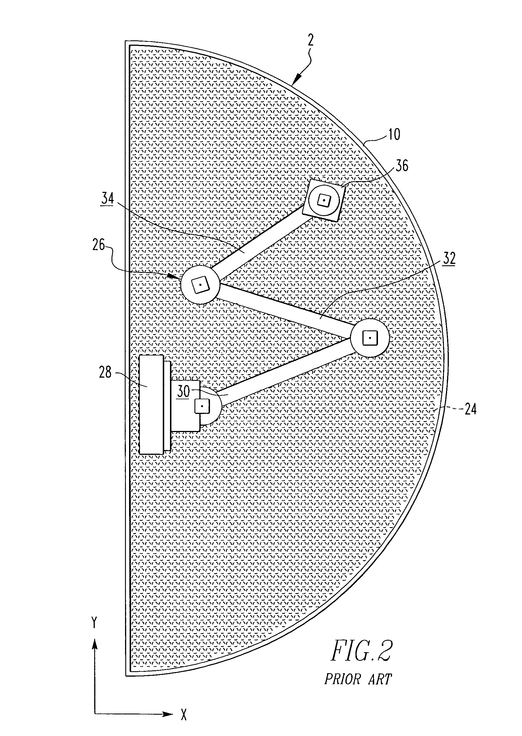
However, while such robotic systems have improved the inspection process, they are relatively deficient at pin-pointing or relocating to a specific tube, in order to, for example, check on the status of the tubes degradation or the integrity of a prior tube repair.
However, such a method requires physical modification of the tubes and is timely and costly to implement, particularly when modifying an existing steam generator to implement the technology.
Mismatched readings indicate a loss of tracking integrity requiring re-calibration of the system.
Such image capturing and analysis systems are susceptible to several disadvantages.
Factors such as illumination and associated shadows, robot arm bending, absence of an adequate reference artifact from which to calculate displacement and camera image distortion caused by, for example, the speed at which the end-effector is traveling and the end-effector's location relative to the tubesheet, can negatively impact the accuracy of the system.
Calibration of robotic inspection systems can be problematic.
For example, it is not uncommon for the robotic arm to be subject to bending forces, particularly when it is fully extended with respect to its mounting location.
Such bending can result in the robotic arm being located at a distance and location different from that calculated by the robot's onboard tube locating encoder or analyzer.
It is, therefore, possible for the wrong tube to be inspected and / or repaired, thereby resulting in the potential of plugging or repairing a perfectly good tube or leaving a degraded tube un-inspected or un-repaired and returning it to service in its degraded condition.
Additionally, known prior art methods of tube identification, whether from the robot or from the tube position verification system, do not update the data collection system to include the current status of the tube for updated future reference.

Method used


Image

  • Method of inspecting a heat exchanger and computer program product for facilitating same
  • Method of inspecting a heat exchanger and computer program product for facilitating same
  • Method of inspecting a heat exchanger and computer program product for facilitating same

Examples


Embodiment Construction

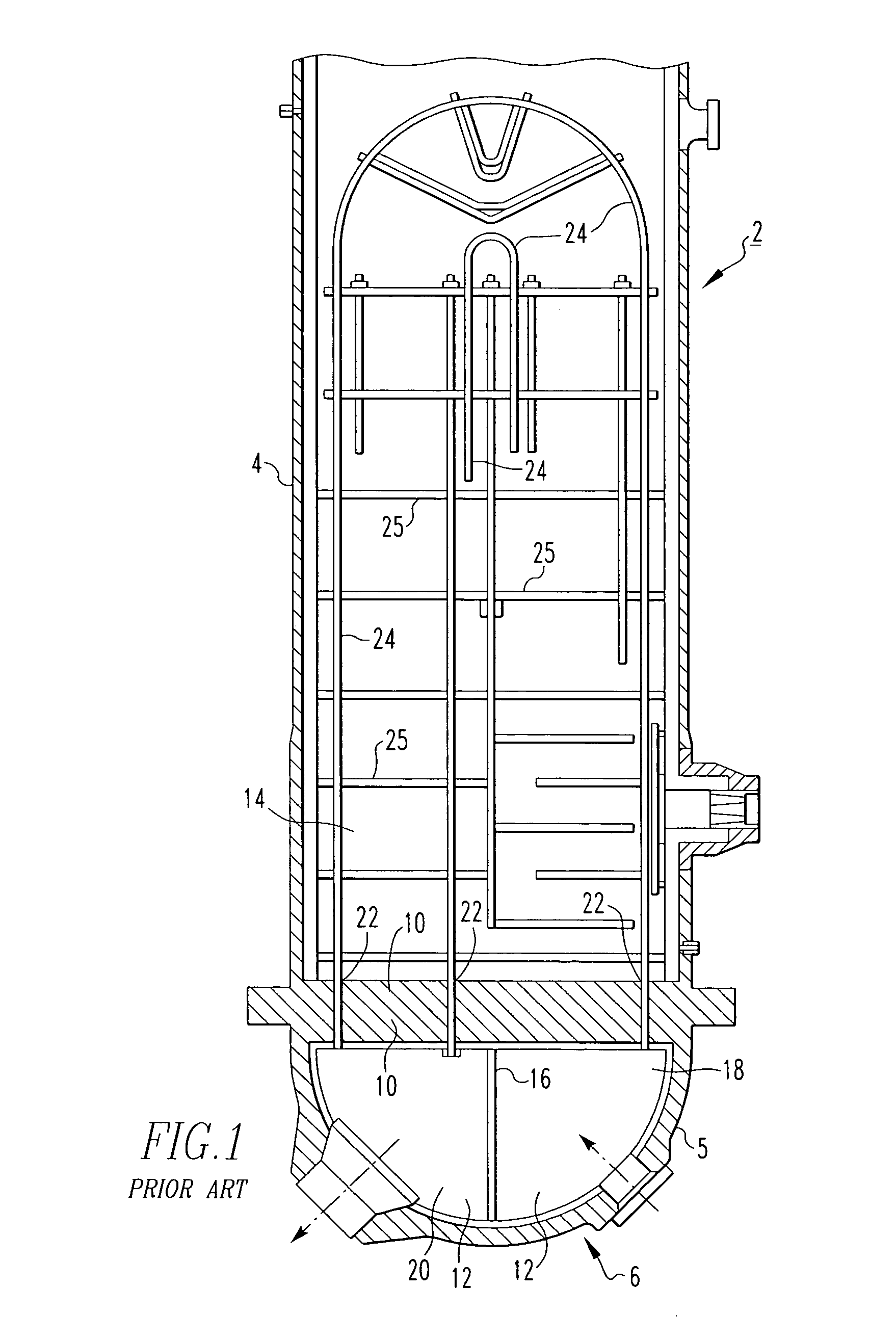
[0035]The invention will be described as applied to U-shaped heat exchanger tubes of a steam generator for a nuclear power generation system, although it will become apparent that it could also be applied to the identification, inspection and repair or servicing of other types of heat exchangers and other applications in which a plurality of generally tubular members are fixed in a transverse plate-like member, such as the exemplary tubesheet.

[0036]It will also be appreciated that while the present invention is described herein with respect to unique tube, tubesheet interface, eddy current patterns and the recording and subsequent referencing of the same, that any suitable alternative signal pattern could be used (e.g., without limitation, x-ray; thermal patterns).

[0037]As employed herein, the term “baseline” refers to a set of data for a heat exchanger tube including, for example, the tube's location in the tubesheet and its unique eddy current signal pattern or fingerprint, which ...


PUM

PropertyMeasurementUnit
eddy currentaaaaaaaaaa
eddy current dataaaaaaaaaaa
eddy current patternsaaaaaaaaaa

Abstract

A method of inspecting a heat exchanger including a plurality of tubes having ends fixed in a tubesheet includes the steps of: establishing a baseline for each tube of its location in the tubesheet and its unique eddy current pattern resulting, at least in part, from fixing the tube end in the tubesheet; inserting an eddy current probe into a first identified tube; obtaining eddy current data for the first identified tube in the region of the tubesheet; comparing the eddy current data obtained for the first identified tube with the baseline eddy current data for the tube, in order to verify the correctness of the tube identification; and accepting the obtained eddy current data if the correctness of the tube identification has been verified by the comparison. A computer program product for automatically carrying out the steps of the foregoing method is also disclosed.

Description

CROSS-REFERENCE TO RELATED APPLICATION[0001]The present application is a traditional application claiming priority to Provisional Application Ser. No. 60 / 535,297, filed on Jan. 9, 2004, entitled “A Method of Inspecting A Heat Exchanger,” which is incorporated herein by reference.BACKGROUND OF THE INVENTION[0002]1. Field of the Invention[0003]The present invention relates generally to a method of inspecting a heat exchanger and, more particularly, to a method of using unique, tube-specific tubesheet eddy current signal characteristics to verify the identity of individual steam generator tubes having ends disposed in a tubesheet. The invention also relates to a computer program product for performing a method of inspecting steam generator tubes.[0004]2. Background Information[0005]Heat exchangers, such as, for example, steam generators used in pressurized water nuclear powered electric generating systems, generally include thousands of U-shaped heat exchanger tubes disposed within a g...

Claims


Application Information

Patent Timeline
Patent Type & Authority Patents(United States)
IPC IPC(8): G06F17/00G06F19/00G01N27/90
CPCG01N27/902
Inventor LE, QUI V.
Owner WESTINGHOUSE ELECTRIC CORP
Learn More