Plastics suction mould and mould making method thereof

A technology of plastic-absorbing molds and molds, which is applied in the field of plastic-absorbing molds in the trial production of automobiles. It can solve the problems that ordinary milling machines cannot be directly processed, reach automotive interior parts, and prolong the processing cycle. The effect of easy processing

Inactive Publication Date: 2009-01-07
JIANGSU GAOBIAO TECH DEV
View PDF0 Cites 6 Cited by
  • Summary
  • Abstract
  • Description
  • Claims
  • Application Information

AI Technical Summary

Problems solved by technology

The use of glass fiber reinforced plastic molds has the advantages of short manufacturing cycle, low cost and suitable for small batch production of parts, but the life is short and easy to deform when heated. The maximum temperature that the mold can withstand is about 80°C or less.
[0004] When making plastic molds, most of them currently use ordinary milling machines or three-axis CNC milling machines. When processing molds, for plastic molds with large sizes and thicknesses, the method of block processing and then bonding imposition is often used, resulting in processing The extension of the cycle and the waste of material costs, the more blocks, the more bonding work, the less guaranteed the dimensional accuracy, and for the shape and characteristics of some mold sides, ordinary milling machines and three-axis CNC milling cannot be directly processed
[0005] In the field of automobile trial production, due to the large size of plastic parts, high precision requirements, and complex shapes, the most important thing is to seek accuracy verification based on the design digital model, and often need to correct the digital model, so the above mold materials and processes cannot be achieved at a low cost. , The production cycle and precision meet the requirements of the trial production of automotive interior parts

Method used


Image

  • Plastics suction mould and mould making method thereof
  • Plastics suction mould and mould making method thereof
  • Plastics suction mould and mould making method thereof

Examples


Embodiment Construction

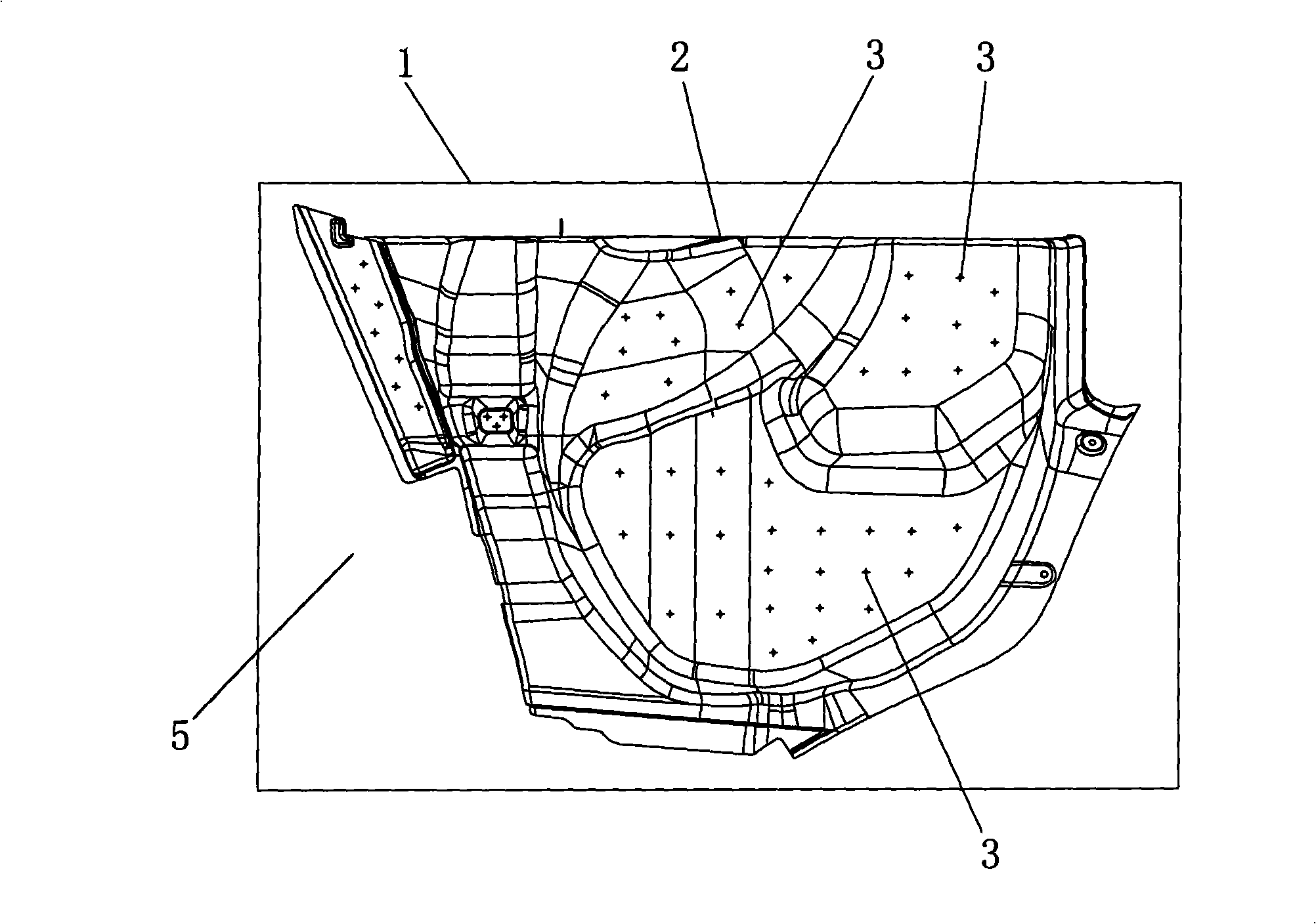
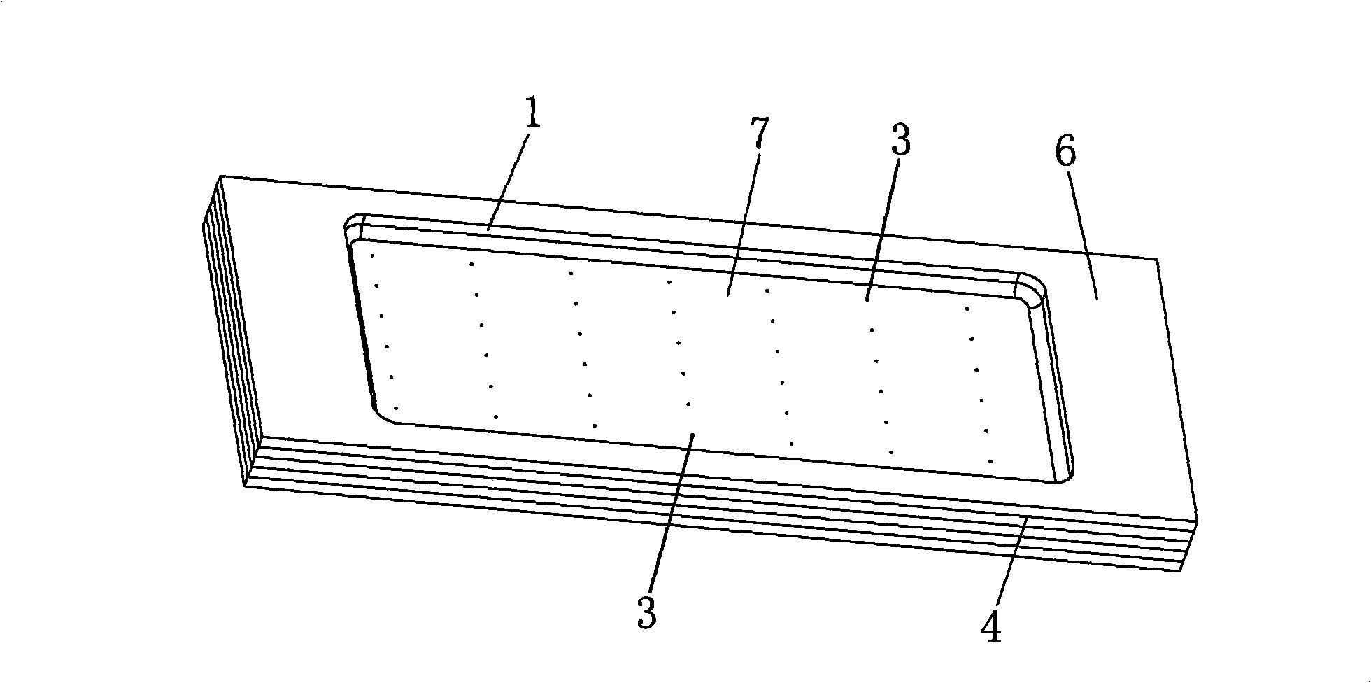
[0024] Such as figure 1 and figure 2 As shown, the blister mold of this embodiment is made of medium density fiberboard 1 , and the medium density fiberboard 1 has multiple layers, and the adjacent layers of medium density fiberboard 1 are bonded by white glue 4 . The blister mold has a front side 5 and a back side 6, the front side 5 is used to process a shape 2, the back side 6 is recessed with a pit 7, the pit 7 is an air chamber 7 that forms a sealing area during plastic suction, and the suction side The back side 6 of the plastic mold is also provided with a plurality of suction holes 3, and the suction holes 3 pass through the front side 5 and the air chamber 7 of the plastic suction mold.

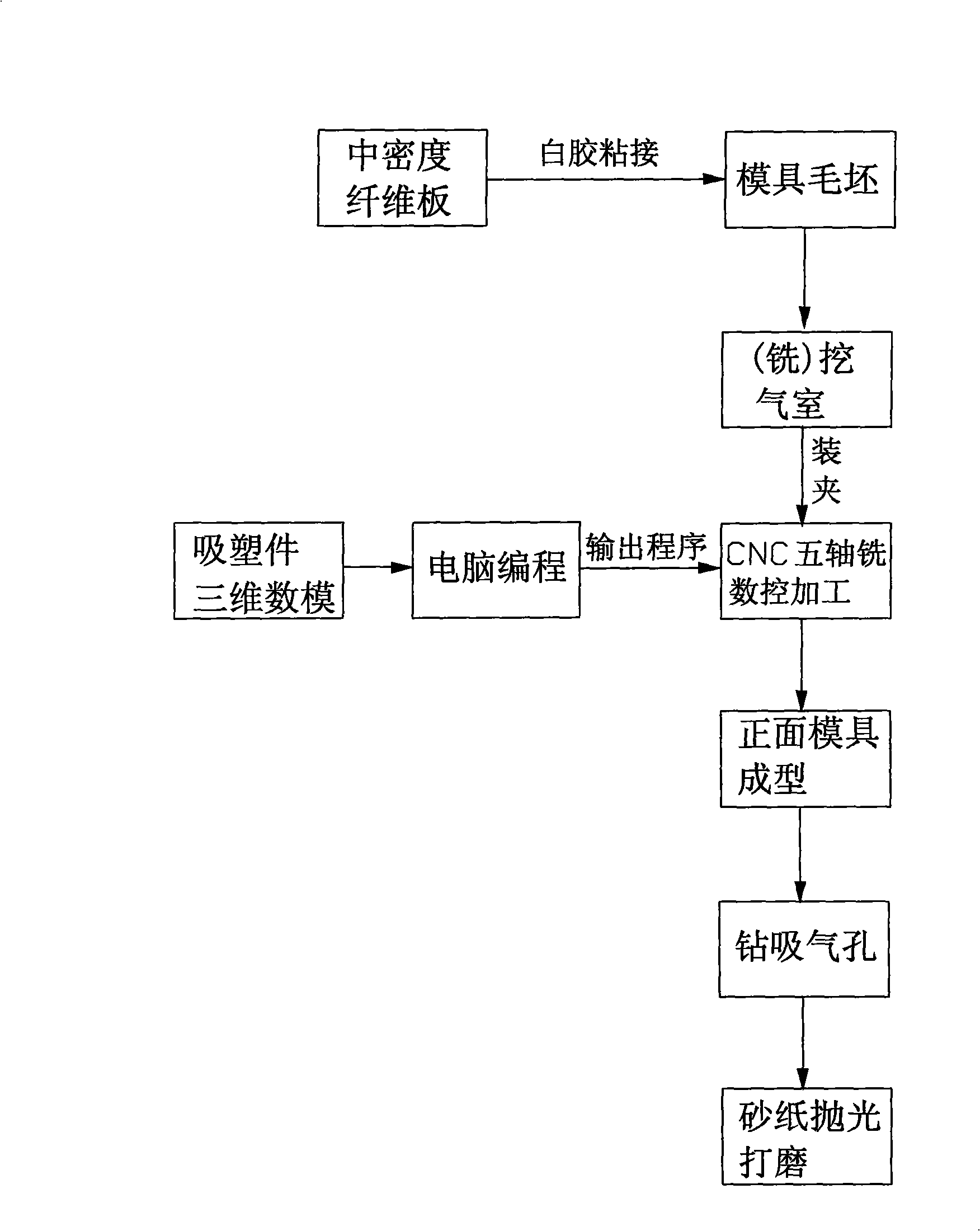
[0025] Such as image 3 As shown, the molding method of the blister mold of the present embodiment includes the following steps:

[0026] a) Extract the three-dimensional digital model of the plastic part to be processed, and use CAM software (such as UG, Powermill, etc.) in the ...


PUM


Abstract

The invention discloses a plastic-sucking mould and a mold making method thereof. The plastic-sucking mould is made of medium-density fiberboards. The mold making method for the plastic-sucking mould comprises the following steps: firstly, the medium-density fiberboards are produced into a mold blank; secondly, a plastic-sucking air chamber is processed on the back of the mold blank; thirdly, a shape is processed on the front side of the mold blank through a multi-shaft numerically controlled milling machine; fourthly, an air sucking hole is drilled on the back of the mold blank, and the air sucking hole is communicated the front side and the air chamber. Because the medium-density fiberboards are adopted as the material of the plastic-sucking mould, the cost is low, the manfuacture of the mold blank is facilitated, the manufacture cycle is short, and the processing and the modification are also facilitated; because the multi-shaft numerically controlled milling machine is adopted for processing, the processing is simple, quick and accurate, and the concave-convex machining precision for the surface of the plastic-sucking mould is high.

Description

technical field [0001] The invention relates to the field of plastic-absorbing molds, in particular to a plastic-absorbing mold in the trial production of automobiles. Background technique [0002] At present, due to the characteristics of low investment cost, suitable for the production of large-sized parts and suitable for products with fast replacement, the blister forming mold is widely used in plastic products, especially in the field of automobile trial production, especially in the production of automobile interior parts. Blister process is mostly used. [0003] Existing manufacturers generally use plaster molds, copper molds, aluminum molds or steel molds when making blister molds, and glass fiber reinforced plastic molds are also used, and which mold to use for mass production is determined according to the output and the complexity of blister molding. It is produced by plaster mold, which has the advantages of short production cycle and the lowest cost. However, t...

Claims


Application Information

Patent Timeline
Patent Type & Authority Applications(China)
IPC IPC(8): B29C51/30B29C33/38
Inventor 程序李会然
Owner JIANGSU GAOBIAO TECH DEV
Why Eureka
Try Eureka