Medical grafting methods and apparatus

a technology of grafting and grafting blood, applied in the field of medical methods and equipment, can solve the problems of long patient recovery time, considerable operation time involved, and patient risks, so as to reduce the need to stop the heart, reduce the need for heart and aorta exposure, and reduce the size of the incision

Inactive Publication Date: 2005-11-01
ST JUDE MEDICAL ATG
View PDF151 Cites 45 Cited by
  • Summary
  • Abstract
  • Description
  • Claims
  • Application Information

AI Technical Summary

Benefits of technology

[0008]It is a further advantage of the invention to reduce significantly the size of the incision and to reduce the exposure of the heart and aorta necessary to perform the surgery.
[0009]It is still a further advantage of the invention to reduce the time necessary to perform the anastomosis procedure by eliminating the time-consuming task of manually suturing the vessels together.
[0010]It is also an advantage of the invention to provide an improved and consistent anastomosis result, without the reliance on the technique and skill of the physician.SUMMARY OF THE INVENTION
[0011]These and other advantages of the invention are accomplished in accordance with the principles of the invention by providing an apparatus and methods for use in making an anastomotic connection between two tubular body fluid conduits in a patient, the connector being configured for attachment to the first and second tubular fluid conduits. In one embodiment of the invention, one of the tubular fluid conduits defines an opening extending between the exterior and the interior of the conduit. The connector may have an interior which is substantially accessible to the interior of the first tubular fluid conduit, and is also configured for annular enlargement. An expandable structure is provided having a first portion configured to annularly enlarge the connector by engaging the interior of the connector. In a preferred embodiment, a second portion of the expandable connector is configured to extend through the opening in the medial portion of the first tubular fluid conduit.
[0012]According to a preferred embodiment, a portion of the connector may be configured for attachment to the axial end of the first tubular fluid body conduit and be substantially coaxial therewith. The connector may include members having free end portions that are configured to penetrate the first tubular body conduit at locations that are axially spaced around the connector. An axial portion of the connector may be configured for insertion through an opening in a side wall of the second tubular fluid conduit. The connector may include members having free end portions that are directed radially outward and are configured to engage the exterior of the side wall of the second tubular fluid conduit when a predetermined axial portion of the connector has passed through the opening in the side wall of the second tubular fluid conduit.
[0013]In order to remotely expand the first, distal portion of the expandable structure, the expandable structure also includes a third, proximal portion for remotely introducing fluid or pressurized air. A tapered structure may be provided for dilating the opening in the second fluid tubular conduit by advancing the tapered structure through the opening. A longitudinal member may be provided which is configured to extend between the first tubular fluid conduit and the second tubular fluid conduit. In a preferred embodiment, the longitudinal member is configured to extend through the opening in the second tubular fluid conduit and along the lumen thereof. The tapered structure may also include an elongated tubular structure, e.g., a catheter-like structure, axially extending from an end portion of the tapered structure and coaxial with the longitudinal member. The tapered structure may be configured to be advanced into and along the interior of the second tubular fluid conduit after dilating the opening in the side wall thereof. Alternatively, the tapered structure is configured to be advanced into and along the interior of the first tubular fluid conduit after dilating the opening in the side wall of the second tubular body conduit. In such a case, the connector may have annularly expanded sufficiently to allow the tapered structure to pass through the interior of the connector. As an alternative or in addition to the tapered structure, a second expandable structure, such as a balloon, may be provided which is configured to dilate the opening in the second tubular fluid conduit.

Problems solved by technology

However, this procedure may involve risks to the patient attributable to the magnitude of the incision required and the procedure of stopping the heart, which allow the physician the access to stitch on a non-beating heart, i.e., “static” stitching.
This procedure may also be associated with various complications, including stroke, heart block, and long patient recovery times. Another factor is the considerable operation time involved due to the criticality of individual hand sewing of each graft end required by the suture process.

Method used


Image

  • Medical grafting methods and apparatus
  • Medical grafting methods and apparatus
  • Medical grafting methods and apparatus

Examples


Embodiment Construction

[0054]Although the invention has other possible uses, the invention will be fully understood from the following explanation of its use in providing a bypass around a narrowing in a patient's vascular system. In addition to providing a coronary artery bypass, the invention is useful anywhere in the patient's circulatory system including renal veins and arteries, femoral veins and arteries, abdominal aorta, peripheral bypass in the arms and legs of the patient, A-V shunts, carotid artery, and any other circulatory system bypass. The bypass graft may be a vein, radial artery, internal mammary artery (IMA), other native vessel, or synthetic conduit.

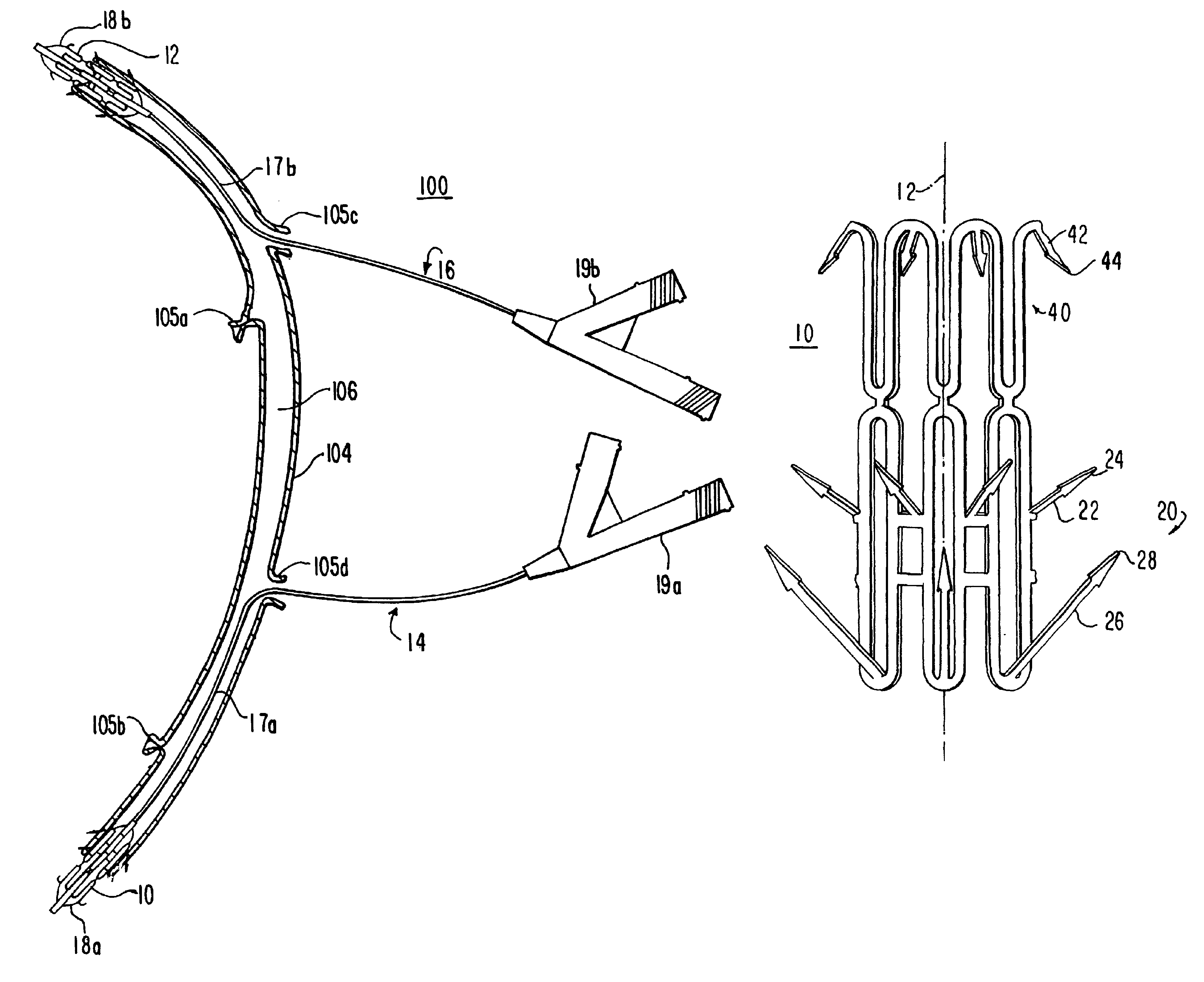
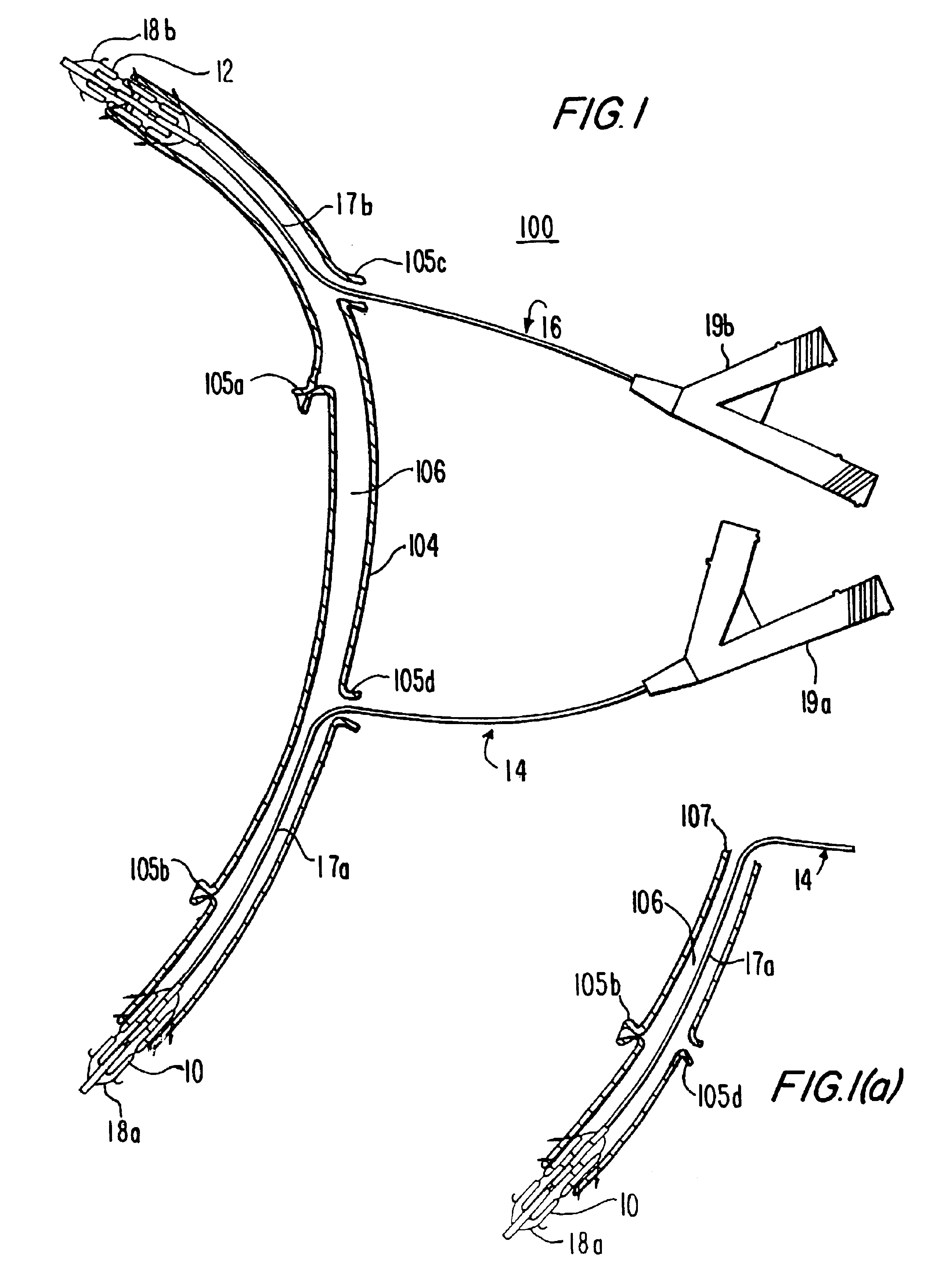
[0055]FIG. 1 illustrates apparatus 100 for installing a graft 104 to the patient's vascular system. Apparatus 100 includes a connector structure 10 useful for making the connection between the graft 104 and the coronary artery (not shown in the FIG.), typically referred to as the “distal” connection. Connector structure 12 is particularly use...


PUM


Abstract

Methods and apparatus for making an anastomotic connection between first and second tubular fluid conduits are provided. For example, a connector may be configured for attachment to the first and second tubular fluid conduits and have an interior thereof substantially accessible to the interior of the first tubular fluid conduit. The connector may be configured for annular enlargement. An expandable structure is provided having a first portion configured to annularly enlarge the connector by engaging the interior of the connector. A second portion may be configured to extend through an opening in the medial portion of the first tubular fluid conduit.

Description

[0001]This application is a division of U.S. patent application Ser. No. 09 / 920,541, filed Aug. 1, 2001 now U.S. Pat. No. 6,511,491, which is a division of U.S. patent application Ser. No. 09 / 324,997, filed Jun. 2, 1999 (now abandoned), which is a nonprovisional of U.S. provisional patent application No. 60 / 123,482, filed Mar. 9, 1999. All of these prior applications are hereby incorporated by reference herein in their entireties.BACKGROUND OF THE INVENTION[0002]This invention relates to medical methods and apparatus, and more particularly to methods and apparatus for installing a tubular graft in a patient for such purposes as bypassing an occlusion or narrowing in the patient's tubular body structure.[0003]The invention is applicable to making anastomotic connections between all body conduits. For example, the invention also has application for attaching coronary artery bypass grafts. Specifically, connection methods and apparatus are provided for attaching the graft ends to the c...

Claims


Application Information

Patent Timeline
Patent Type & Authority Patents(United States)
IPC IPC(8): A61B17/11A61B17/03A61B17/064A61F2/06F16L11/12F16L55/00
CPCA61B17/064A61B17/11A61F2/064A61B2017/0641A61B2017/1107A61B2017/1135Y10S623/903
Inventor GRUDEM, JERRYSWANSON, WILLIAM J.BERG, TODD ALLEN
Owner ST JUDE MEDICAL ATG
Why Eureka
Try Eureka