Device for applying varnish to electric wire and method of applying varnish

a technology for varnishing devices and electric wires, applied in the direction of insulating conductors/cables, cables, insulated conductors, etc., can solve the problems of loss of insulation performance, difficulty in maintaining the quality of varnish, and difficulty in continuous maintenance of varnish viscosity, etc., to achieve excellent electric and heat insulation performance, maintain the quality of varnish, and the effect of sufficient applicability

Inactive Publication Date: 2005-11-01
GOTO DENISH CO LTD
View PDF13 Cites 12 Cited by
  • Summary
  • Abstract
  • Description
  • Claims
  • Application Information

AI Technical Summary

Benefits of technology

[0011]An object of this invention is to provide a device and method for applying varnish to an electric wire, which provides a little amount of solvent which volatizes with passage of time so that the mixing rate of resin component to the solvent component in the varnish is always maintained constant to maintain the viscosity of the varnish, thereby providing sufficient applicability to the electric wire, can maintain the quality of the varnish to make it difficult to generate pin holes, cracks, etc., provides excellent electric and heat insulation performance, can easily manage and inspect the quality of the varnish to provide improved production yield and production efficiency, and provides a simple structure which can be easily handled with reduced production cost.
[0020]Such configurations can provide a little amount of solvent which volatizes with passage of time so that the mixing rate of resin component to the solvent component in the varnish is always maintained constant to maintain the viscosity of the varnish, thereby providing sufficient applicability to the electric wire, can maintain the quality of the varnish to make it difficult to generate pin holes, cracks, etc., provides excellent electric and heat insulation performance, can easily manage and inspect the quality of the varnish to provide improved production yield and production efficiency, and provides a simple structure which can be easily handled with reduced production cost.
[0024]In this configuration, exchange and cleaning, fine adjustment of location of the container and other components the container can be easily carried out.
[0031]In this configuration, by simply operating the operating knob, the internal aperture of the dropping nozzle can be adjusted, thereby adjusting the quantity of the varnish to be dropped toward the outer surface of the electric wire easily and surely. Further, the flow-rate adjusting means permits the vaporizing of the solvent to be suppressed and the mixing rate of the resin component to the solvent component to be maintained constant, thereby displaying the viscosity of the varnish effectively.
[0032]Since the guiding member is slidably fit in the outside of the nozzle holder in a direction orthogonal to the moving direction of the electric wire, fine adjustment of the location of the dropping nozzle can be carried out easily, surely and accurately.

Problems solved by technology

Thus, it was difficult to maintain the viscosity of the varnish continuously to keep the applicability of the varnish to the electric wire effectively.
In addition, as described above, the solvent is likely to be volatized so that it is difficult to maintain the quality of the varnish.
The performance of insulation may be also lost and cracking is likely to occur, thereby reducing the production yield.
Such management or inspection of the density or viscosity of the varnish consumes much labor and time to form the insulating layer of varnish on the outer surface of the electric wire, thereby reducing the production efficiency.
In the above other method of applying the varnish onto the outer surface of the electric wire using the roller, the varnish is excessively stirred by the roller which is rolled in the tank.
Accordingly, it is difficult to validate the applicability of the varnish to the electric wire by e.g. maintaining the viscosity of the varnish in an easily applicable state, and maintain the quality of the varnish.
As a result, the varnish applied to the outer surface of the electric wire lacks an insulting performance, is apt to crack, which results in the product with low production yield.
Further, the varnish is not applied to have a uniform thickness but applied unevenly.
This generates cracks so that the insulating layer is apt to deteriorate, thereby loosing the electric insulation and heat insulation performance.

Method used


Image

  • Device for applying varnish to electric wire and method of applying varnish
  • Device for applying varnish to electric wire and method of applying varnish
  • Device for applying varnish to electric wire and method of applying varnish

Examples


concrete example 1

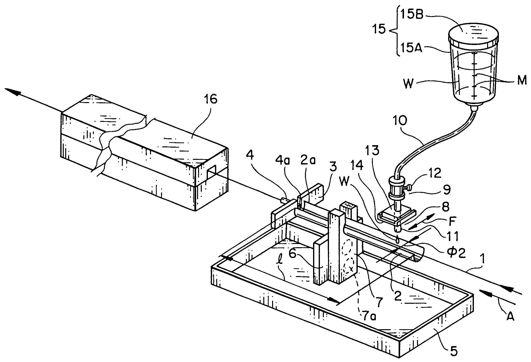
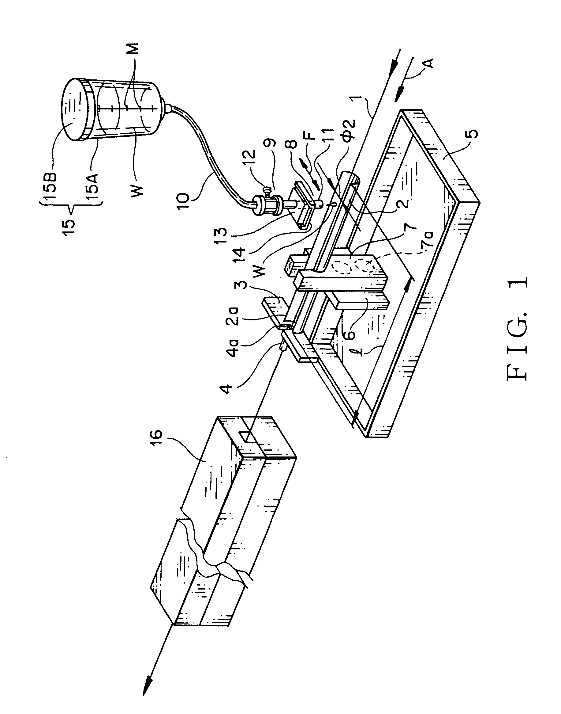
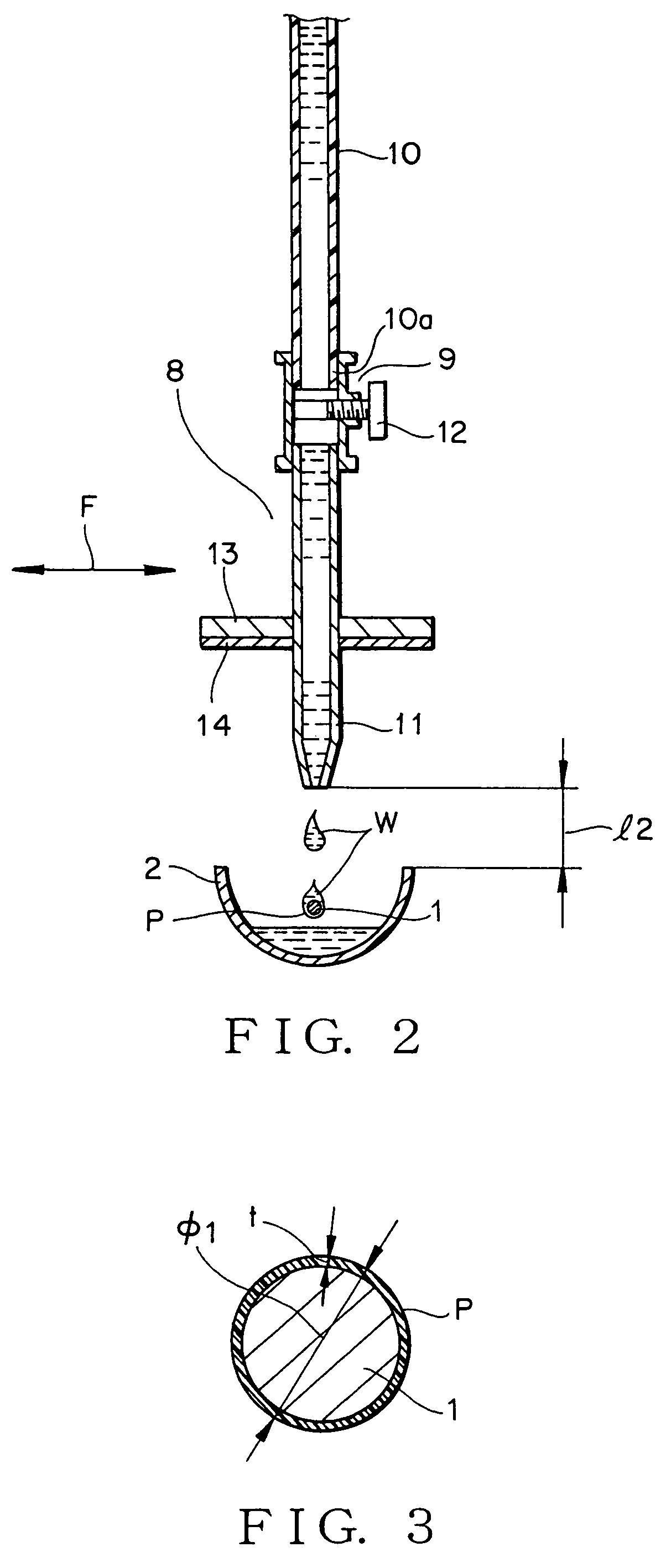
[0080]By rolling the supplying roller not shown so that an electric wire having an outer diameter φ of 1.00 mm is supplied and taking up the electric wire by the take-up reel not shown, the electric wire is moved at a speed of about 20 m / minute. By tuning the operating knob 12 of the dropping means 8, from the dropping nozzle 11, a suitable quantity of the varnish W contained in the tank 15 is dropped one drop by one drop onto the electric wire 1 which is moving in the moving direction A.

[0081]In this case, the varnish W is composed of the resin component which is a compound of one or two kinds of resins of e.g. polyamide, epoxy, polyimide, etc. and the solvent of cresol, xylene, xylol, ethylbenzene, phenol, methanol, ethanol, water, etc. In this embodiment, the varnish W is composed of the resin component of 10–30% by weight and solvent of 70–90% by weight. In this case, the varnish W has the resin component of 10.0–30.0% by weight and the viscosity of 1.0–35 dPa·s at the varnish l...

concrete example 2

[0094]By rolling the supplying rollers not shown so that plural electric wires (three wires in FIG. 4) 1, 1, . . . are supplied and taking up the electric wires by the take-up reels not shown, the electric wires are moved at desired speeds of about 15–20 m / minute in the moving direction A. By tuning the operating knob 12 of the dropping means 8 for each of the electric wires 1, 1, . . . , from each of the dropping nozzles 11, a suitable quantity of the varnish W contained in each of the tanks 15 is dropped one drop by one drop onto the electric wires 1, 1, . . . which are moving in the moving direction A.

[0095]The varnish W with the density and viscosity adjusted is accommodated within the sealed tanks 15, 15, . . . and is exposed to the open air after it has dropped through the supplying tube 10 from the dropping nozzle 11. Therefore, the solvent whose rate adjusted to the resin component volatizes in a small quantity with passage of time. The mixing rate of the resin component to ...


PUM

PropertyMeasurementUnit
moving speedaaaaaaaaaa
lengthaaaaaaaaaa
outer diameter φ2aaaaaaaaaa

Abstract

An electric wire 1 is moved in a moving direction at a desired speed. An insulating layer of varnish is formed on the outer surface of the electric wire 1 by a device for applying the varnish. The device includes a rough-like container 2 and dropping means 8. The rough-like container 2 is located below the electric wire 1 in the moving direction. The dropping means 8 is located for the electric wire above the container. A desired quantity of varnish is dropped from the dropping means 8 toward the outer surface of the electric wire 1 through a flow rate adjusting portion. The flow rate of the varnish is adjusted by the flow rate adjusting portion 9.

Description

BACKGROUND OF THE INVENTION[0001]1. Field of the Invention[0002]This invention relates to a device and method for applying varnish to an electric wire, and more particularly to a device and method for forming an insulating layer with sure electric and heat insulation by applying a necessary minimum amount of varnish to the outer surface of an electric wire with no change in the mixing rate of resin and solvent in the varnish with good productivity.[0003]2. Description of the Related Art[0004]A previously known method for forming an electric insulating layer or a surface treated layer on the outer surface of an electric wire is to immerse the electric wire in an insulating liquid such as varnish by passing the electric wire through the tank containing the insulating liquid so that the varnish is applied to the outer surface using the viscosity of the varnish to form an insulating layer, and to dry the insulating layer of the varnish by passing the electric wire through a dry furnace ...

Claims


Application Information

Patent Timeline
Patent Type & Authority Patents(United States)
IPC IPC(8): B05C3/02B05C3/12B05C5/00H01B13/16H01B13/06H01B7/02H01B7/00H01B7/29
CPCH01B7/292H01B13/06H01B13/065H01B13/16Y10S118/22Y10S118/19
Inventor GOTO, YOSHIHIDE
Owner GOTO DENISH CO LTD
Why Eureka
Try Eureka