Insulating switching DC/DC converter

a technology of dc/dc converter and switching dc/dc, which is applied in the direction of electric variable regulation, process and machine control, instruments, etc., can solve the problems of large volume of the core and low efficiency of the overall apparatus, and achieve high-efficiency apparatus, reduce the volume of the core, and reduce the loss of the core

Inactive Publication Date: 2005-11-01
DENSO CORP
View PDF4 Cites 10 Cited by
  • Summary
  • Abstract
  • Description
  • Claims
  • Application Information

AI Technical Summary

Benefits of technology

[0012]The present invention is developed in view of such circumstances and has its object the provision of a switching DC / DC converter which reduces the core volume and core losses of magnetic components and improves the efficiency of the overall apparatus.
[0014]According to the present invention, in the DC / DC converter using an insulating transformer having the center tap on the secondary side, the input choke coil and the output choke coil are integrated with the insulating transformer, the primary coil and the secondary coil of the transformer and the input / output choke coils are wound around the same core (magnetic core), and the number of turns and the winding directions of the coils are designed in directions of canceling DC fluxes generated by the coils, so that the DC biased magnetization of the core is considerably reduced. Thus, it is possible to greatly miniaturize the volume of the core and reduce core losses as compared with the conventional art, thereby achieving a high-efficiency apparatus.
[0020]As described above, according to the present invention, in the insulating switching DC / DC converter using the center tap method or the combined transformer that have a plurality of coils on the secondary side of the transformer, the input choke coil and the output choke coil are integrated with the insulating transformer, the primary coil and the secondary coil of the transformer and the input / output choke coils are wound around the same core, and the coils are arranged in directions of canceling DC fluxes generated by the coils, so that the DC bias magnification of the core is greatly reduced. Thus, it is possible to considerably reduce the volume of the core and reduce core losses as compared with the conventional art, thereby achieving a high-efficiency apparatus.

Problems solved by technology

However, in the circuit configurations having been conventionally proposed, although the output is reduced in ripple voltage and ripple current, the core of magnetic components (input choke coil, output choke coil, and transformer) is considerably increased in total DC bias magnetization, so that the core has a large volume and the overall apparatus has low efficiency.

Method used


Image

  • Insulating switching DC/DC converter
  • Insulating switching DC/DC converter
  • Insulating switching DC/DC converter

Examples


Embodiment Construction

[0050]Preferred embodiments of the present invention will be described in detail in accordance with the accompanying drawings.

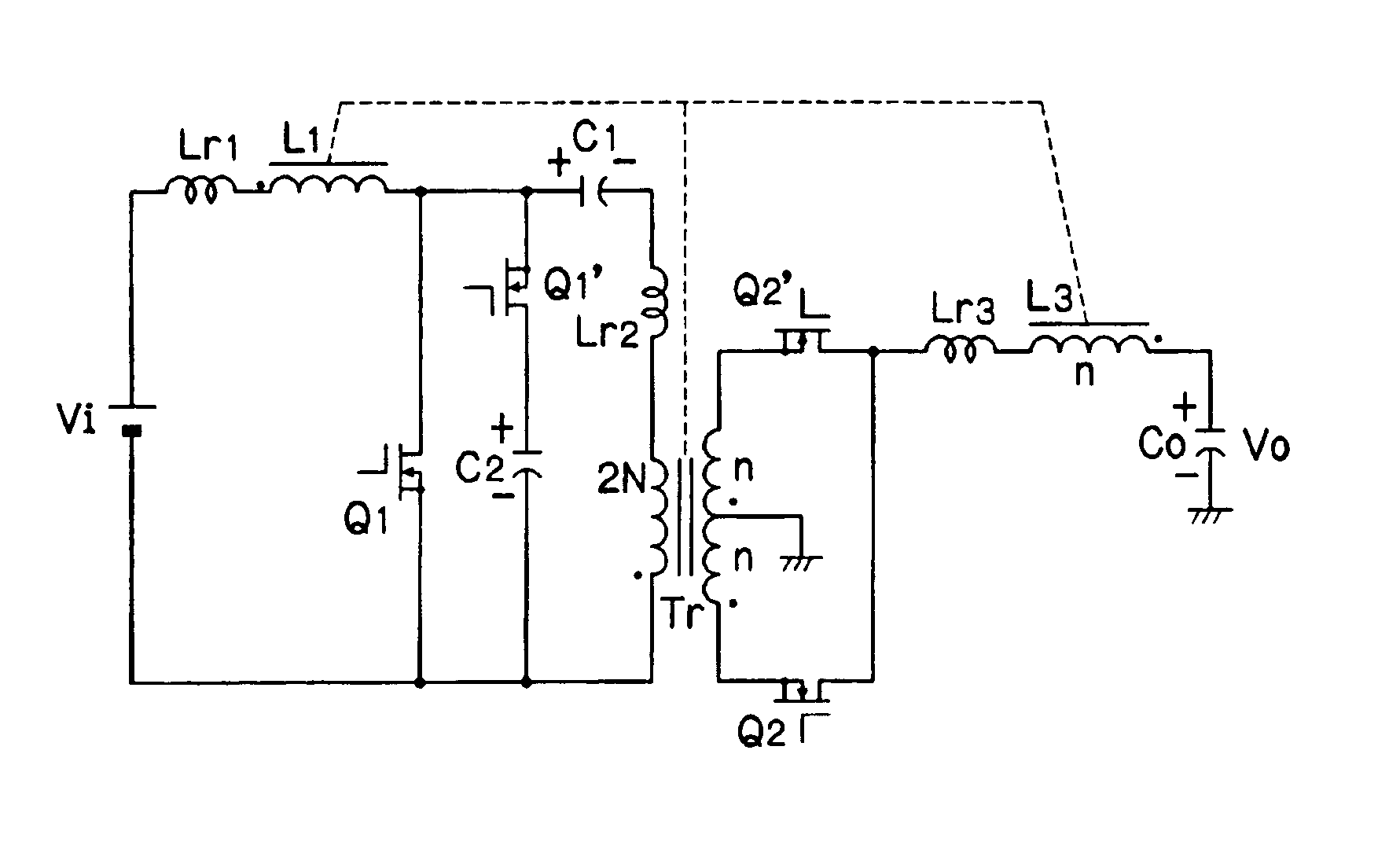
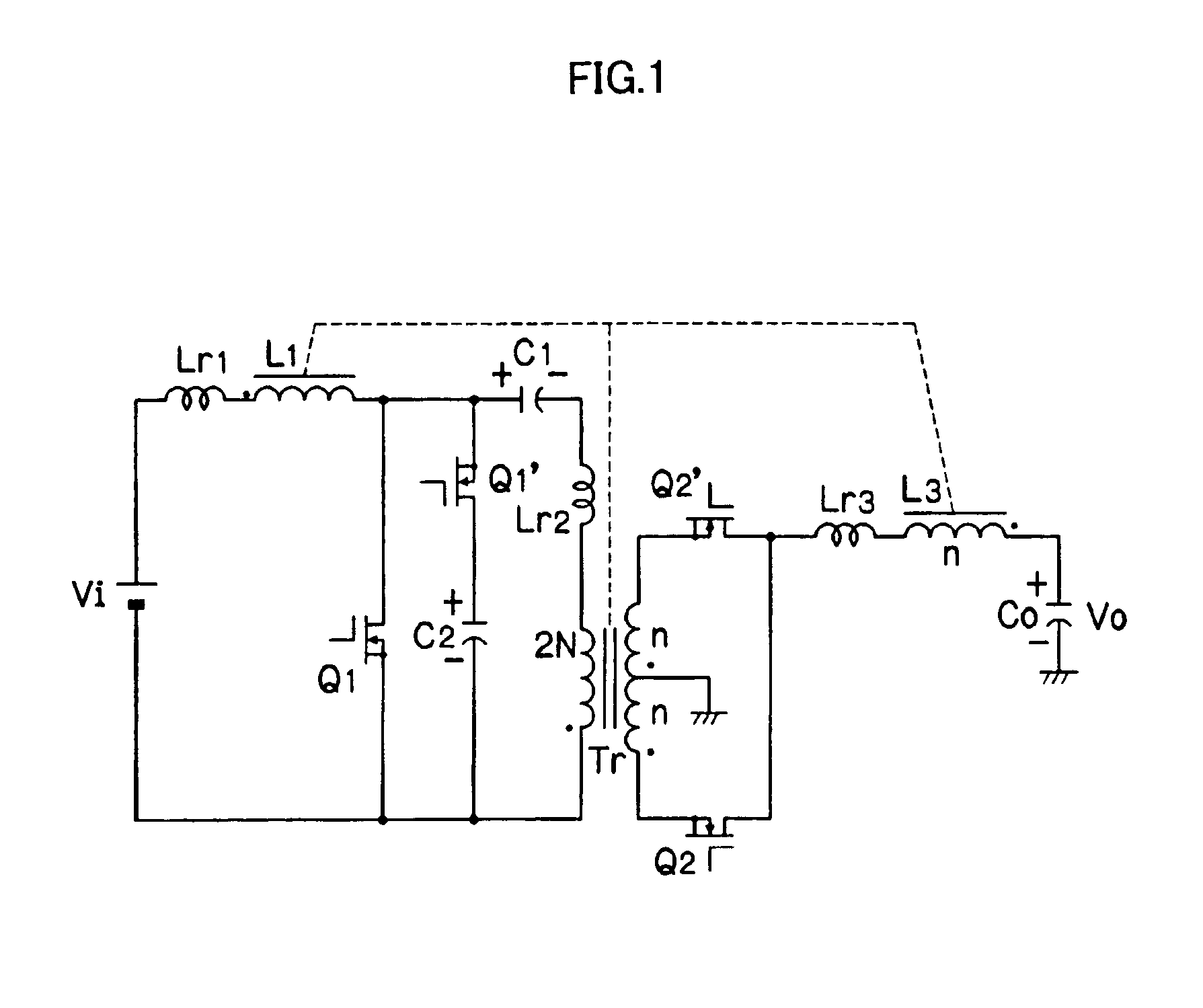
[0051]FIG. 1 is a circuit diagram showing a DC / DC converter (step-up active clamp half-bridge converter). In FIG. 1, reference character Vi designates an input power supply, reference numeral Lr1 designates a leakage inductance, reference numeral L1 designates an input choke coil (2N: the number of turns, N: natural number), reference numerals Q1 and Q1′ designate switching devices using FETs, reference numeral C1 designates a DC component removing capacitor, reference numeral C2 designates a clamp capacitor, reference numeral Lr2 designates a leakage inductance, reference character Tr designates an insulating transformer having a center tap on the secondary side (2N: the number of turns of a primary coil, n, n: the number of turns of a secondary coil, n: natural number), reference numerals Q2 and Q2′ designate switching devices acting as synchronous rectifyi...


PUM


Abstract

In a DC / DC converter using an insulating transformer Tr having a center tap on the secondary side, an input choke coil L1 and an output choke coil L3 are integrated with the insulating transformer Tr, a primary coil (number of turns: 2N) and a secondary coil (number of turns: n+n) of the transformer, the input choke coil L1 (number of turns: 2N), and the output choke coil L3 (number of turns: n) are wound around a common core (magnetic core), and the coils are arranged in directions of canceling DC fluxes generated by the coils, so that the DC bias magnetization is considerably reduced.

Description

BACKGROUND OF THE INVENTION[0001]1. Field of the Invention[0002]The present invention relates to a switching power supply and particularly relates to a technique for achieving higher efficiency and miniaturization of an insulating switching DC / DC converter.[0003]2. Description of the Related Art[0004]Conventionally switching power supply circuits using the Boost Half Bridge (BHB) method are proposed in which a booster circuit and a half bridge circuit are integrated (Reference 1, Reference 2, Reference 3, Reference 4). FIG. 29 shows a circuit configuration proposed in Reference 3. In FIG. 29, reference character E designates an input voltage source, reference numeral L1 designates an input choke coil, reference numeral L2 designates an output choke coil, reference numeral C0 designates an output smoothing capacitor, reference numeral R0 designates a load resistance, and reference numeral V0 designates an output DC voltage.[0005]According to the circuit of the BHB method shown in FIG...

Claims


Application Information

Patent Timeline
Patent Type & Authority Patents(United States)
IPC IPC(8): H02M3/335H02M3/24H02M3/28
CPCH02M3/33569H02M2001/0064H02M2007/4803H02M1/0064H02M7/4803H02M3/33571H02M3/01
Inventor TAMURA, YOSHIMOTO
Owner DENSO CORP
Why Eureka
Try Eureka