Pumped laser and optimized lasing medium
Inactive Publication Date: 2005-11-01
THALES SA
14 Cites 0 Cited by
AI-Extracted Technical Summary
Problems solved by technology
The high value of the extent in the plane D// and the great dissymmetry between D// and D⊥make it difficult to design optical systems for the focusing of light emitted with the active lasing medium.
At output of an optical system such as this, the light is highly divergent and this is inconvenient because:the oscillation threshold of the laser increases with the volume in which the pump energy is deposited, and,a multimode operation may be induced if this volume is greater than the volume take...
Benefits of technology
[0022]It relies also on the association of a simple optical focusing system that comprehensively...
Abstract
A longitudinally pumped laser including one or more active lasing media arranged in an optical laser cavity and at least one pumping device emitting at least one pumping beam toward the at least one active lasing medium. The pumped beam or beams is coupled with the active medium. At least one of the active lasing media includes one or more non-homogeneously doped zones, and the dimension of the doped zones and/or the distribution of the dopants is chosen on the basis of the desired transverse mode of the laser cavity. Such a laser can be used as an amplifier.
Application Domain
Laser using scattering effectsSemiconductor laser arrangements +4
Technology Topic
Active mediumOptoelectronics +5
Image
Examples
- Experimental program(1)
Example
[0051]To provide for a clearer understanding of the principle of operation of the laser according to the invention, the following description, given by way of an illustration that in no way restricts the scope of the invention, relates to a diode-pumped laser associated by means of a simple coupling optical system with a non-uniformly doped active lasing medium, in particular to favor the transverse TEM00 mode of the laser cavity.
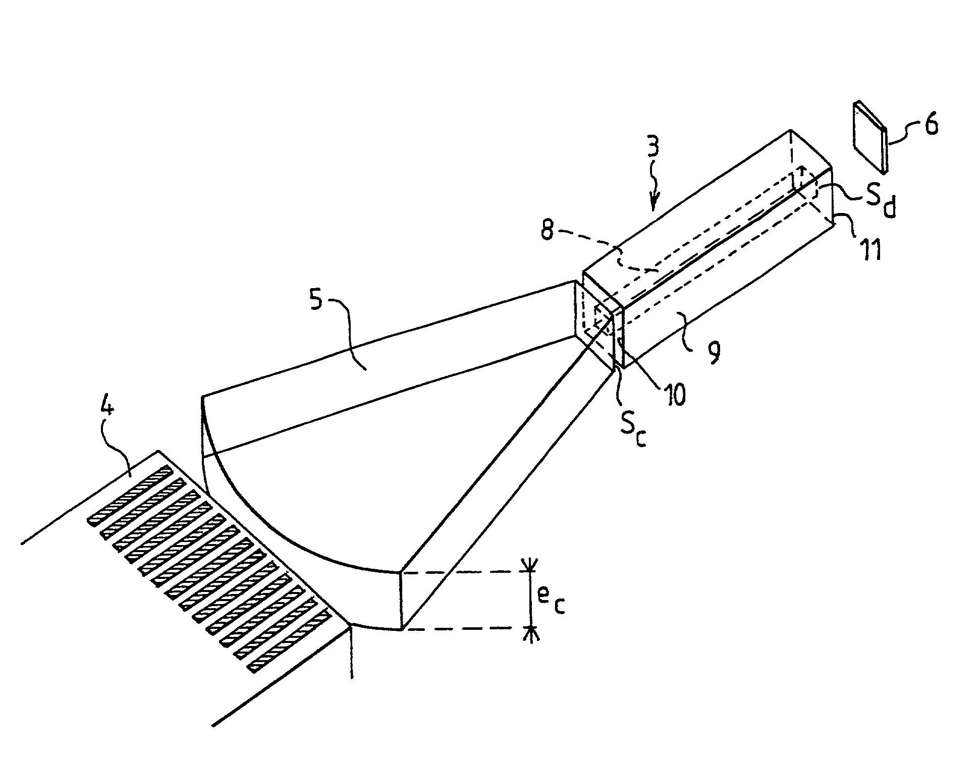
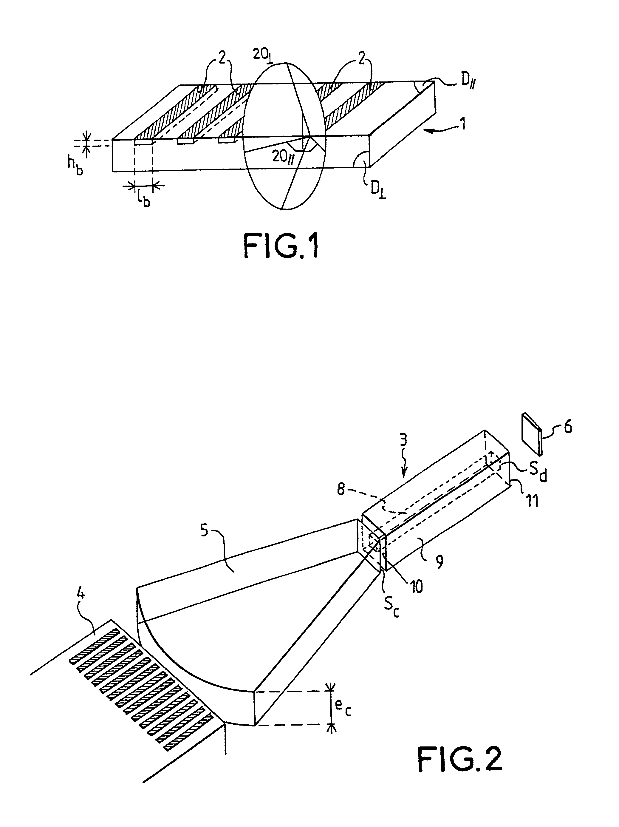
[0052]FIG. 2 shows an exemplary architecture of a laser module according to the invention. This module consists of a non-homogeneously doped active lasing medium 3 that favors a particular laser mode such as the transverse TEM00 mode, a pump laser diode 4, means 5 for coupling the pump beam coming from the pump laser diode 4 to the active lasing medium 3. The laser cavity is closed by a mirror 6.
[0053]The mirror 6 is positioned for example in the optical axis of the laser, perpendicularly to the laser beam. It has transmission characteristics suited to optimizing the working of the laser.
[0054]Pump Laser Diode
[0055]The pump laser diode 4 may be a unitary laser diode, or an assembly of laser diodes (linear arrays, stack of linear arrays, surface emission plates etc) as described for example in FIG. 1, or again any assembly of diodes or unitary diodes. The beam emitted by such a structure is for example reshaped before it is transmitted to the active lasing medium.
[0056]The laser diode may also take the form of several linear arrays positioned in such a way that the emission takes place in all three dimensions. An example of such a structure is given in FIG. 4. Such a structure may be used with or without a coupling optical system.
[0057]Coupling Means
[0058]The coupling means 5 are adapted to the type of pump laser diode used. For longitudinal type pumping, it is possible for example to use a light concentrator as described in one of the following references: [0059] [1]“High efficiency TEM00 Nd:YVO4 laser longitudinally pumped by a high power laser diode array”, SPIE Proceedings, [0060] [2] G. Feugnet, C. Bussac, M. Schwartz, C. Larat and J. P Pocholle “Nonimaging optics III: Maximum Efficiency Light Transfer”, in Opt. Lett. 20, pp 157–159, 1995.
[0061]The dimension of the concentrator 5 corresponding to the width of the laser rod in the parallel plane D// is equal, for example, to 1.5 mm. The thickness ec of the light concentrator is substantially constant and equal to 1.5 mm. The output face of the concentrator has a square section sc substantially equal to (1.5*1.5) mm2.
Active Lasing Medium
[0062]The active lasing medium 3 is formed, for example, by a composite rod comprising a doped central region 8 having a parallelepiped shape with a square section sd, for example, surrounded by a non-doped peripheral region 9, namely a zone having practically no dopant and even no dopant at all.
[0063]The dopant used for the active medium is chosen, for example, from among one or more of the ions of the following list: (Nd3+, Yb3+, Er3+, Ho3+, Th3+, . . . ).
[0064]The active lasing medium is, for example, a solid medium that has several laser transitions (YAG:Nd, YVO4:Nd, sapphire:Ti, etc) and is known to those skilled in the art.
[0065]The doped zone 8 has a length Ld substantially equal to the length Ll of the active lasing medium, a section sd, and a volume Vd corresponding to sd*Ld. The pump light is deposited or absorbed in this volume Vd, for example according to the scheme described in FIGS. 3a and 3b.
[0066]The doped zone 8 has dimensions adapted to the fundamental mode of the laser cavity for example. These dimensions may also be fixed so as to promote the appearance of other transverse modes. Its length is for example chosen as a function of the quantity of light to be deposited and of the absorption.
[0067]Determining the Dimensions of the Doped Zone
[0068]One way to determine the geometry and the dimensions of the non-uniformly doped zone and/or the distribution of the dopants comprises, for example, the following steps: [0069] From the characteristics of the emissive source (the laser diode) such as its dimensions, its divergence values etc., an optical focusing system is designed. The optical focusing system is determined, for example, so that its transmission is as efficient as possible, according to criteria known to those skilled in the art. Typically, the light is focused on a spot whose section sl is some square millimeters, [0070] The section of the non-uniformly doped rod is adapted to the dimensions of the light spot. [0071] For example, the section of the rod may be substantially square, equal to or slightly greater than that of the output face of the concentrator, [0072] For a cylindrical rod, the diameter is substantially equal to or slightly greater than the diagonal of the output face of the concentrator, [0073] The dimensions may also be chosen to take account of the positioning tolerances of the rod with respect to the concentrator and the quality of the edges of the rod. [0074] In the case of a focusing that uses a lens, the section of the rod is adapted so that the transmission T through a fictitious aperture with identical dimensions is in the range of 100% with
T=∫∫aperture sectionI(x,y)dxdy/∫∫∞I(x,y)dxdy
where I(x,y) is the distribution of the intensity at the focusing point of the light, [0075] The ratio r between the dimensions of the doped zone and those of the non-doped zone is defined in taking account of the characteristics of the pump radiation taken after the optical coupling system 5, the spectroscopic characteristics of the laser material and the technological constraints related to the making of the non-uniformly doped rod. The spectroscopic characteristics of the laser material may be recorded during preliminary tests using methods known to those skilled in the art. [0076] The process of determining the ratio r takes place, for example, iteratively, and comprises, for example, the following steps: [0077] during a first step a), fixing the value of the ratio r at a value r0, [0078] computing (second step b)) the pump energy distribution in the rod and the associated thermal effects from this value in implementing a ray tracing program and a thermal computation program, [0079] during a third step c), designing a laser cavity whose TEM00 mode is close to the dimensions of the doped zone, for example by means of a laser cavity computation program taking account of the thermal effects, [0080] If the TEM00 mode determined is different or far too remote, changing the initially chosen ratio and restarting the steps a) to c). The value of the length of the laser cavity may indeed be limited for reasons of space requirement.
[0081]The different computation methods implemented in the steps described here above are known to those skilled in the art.
[0082]When determining the value of the ratio r, it is necessary to take account of the following constraints: [0083] the influence of its value on the rod length needed to absorb the energy, it being known that the length may be limited for reasons of technology, [0084] the influence of its value on the energy absorbed per unit of length which must remain much below the optical damage threshold.
[0085]To obtain efficient discrimination between the fundamental mode of the cavity and the higher-order modes, thus favoring the TEM00 operation, the dimensions of the doped zone are chosen as a function of the dimensions of the fundamental mode of the laser cavity.
[0086]Thus, the section sd of the doped zone is preferably smaller than or equal to the section sm of the fundamental mode of the cavity. It may also be slightly greater than or greater than the section of the fundamental mode associated with another selection device.
[0087]The section sm of the fundamental mode corresponds, for example, to the section of the laser beam taken at about 13.6% of the maximum.
[0088]The steps described with reference to a square geometry may also be applied in the case of a cylindrical geometry, in assuming, in this case, the cylindrical section of the doped zone.
[0089]The interface between the doped zone 8 and the peripheral zone 9 will be made so as to minimize the losses like to hamper or impair the operation of the laser according to techniques known to those skilled in the art.
[0090]The dimensions of the peripheral zone 9 are chosen, for example, as a function of the performance characteristics of the focusing optical system, for example the focusing spot, the divergence of the radiation after the focusing point. The section Snd and Sd is substantially equal to the section Sc of the face of the concentrator positioned before it. The length Lnd of the non-doped zone corresponds, for example, to the length of the material or active medium forming the laser. It may correspond to the length Ld of the doped zone.
[0091]Without departing from the framework of the invention, the doping may also be obtained in the form of a gradient of dopants distributed non-homogeneously in the material forming the active medium. The gradient, the distribution of the dopants as well as their nature will be determined according to the mode of operation chosen for the laser.
[0092]According to another alternative embodiment, the rod comprises a totally non-doped section at least at one of its ends. With this technique, it is possible to reduce the deformations at the ends of a rod. The contact between the non-doped sections and the non-homogeneously doped sections may be obtained by a diffusion bonding technique known to those skilled in the art.
[0093]The two external face 10, 11 of the composite rod are polished so as to guide the pump light by total or practically total reflection.
[0094]The face 10 of the composite rod that is facing the concentrator 5 is provided with a treatment that makes it anti-reflective at the pumping wavelength and totally reflective at the laser wavelength.
[0095]The opposite face 11 of the rod is treated to be anti-reflective at the laser wavelength. This face may be angle-polished so that the beam has an angle of incidence with a value close to the Brewster's value. During the mounting of the laser rod, the necessary precautions will be taken to prevent a part of the beam from getting propagated in another attached medium.
[0096]FIGS. 3a and 3b give a schematic view of an exemplary path of the pump light in the active lasing medium comprising a parallelepiped shaped central doped zone as shown in FIG. 2. During its propagation in the laser rod, the laser beam does not necessarily cross the non-doped zone at each reflection. The power of the pump is deposited solely in the central doped zone, thus favoring the TEM00 operation. Furthermore, a structure of this kind overcomes the divergence of the pump light incident on the composite medium.
[0097]Thus, on the paths 12 shown in dotted lines, there is no absorption of light whereas on the paths 13 of the light rays shown in solid lines, the light ray is absorbed. The pump light is guided by reflection on the lateral faces of the lasing medium, by total internal reflection or by reflection on a dielectric treatment, and thus makes a zigzag path in the composite rod, in depositing the energy solely in the doped zone 8. After a sufficient number of reflections, all the power of the pump will be absorbed.
[0098]The geometry (shape and dimensions) of the non-doped zone is adapted to optimizing the number of beams that cross it while at the same time providing for guidance by total reflection.
[0099]In comparison with the highly doped structures mentioned here above, the pump power is distributed in a volume greater than that usually offered by prior art lasers. This especially reduces the aberrations, constraints and birefringence arising out of thermal causes.
[0100]According to another alternative embodiment, the active medium comprises the non-doped central zone and a dope peripheral zone. In this case, the light path will deposit energy no longer centrally but on the periphery of the composite rod, thus favoring the higher-order modes. This arrangement favors the mode usually known as the ring mode.
[0101]According to another variant, known for example in the field of what are called “double clad” fibers, described for example in the U.S. Pat. No. 4,815,079, the doped zone is off-centered with respect to the zone that guides the pump or again the guiding zone has a particular shape, for example a D shape.
[0102]With these embodiments, which consist in breaking the symmetry of the optimized medium, the number of the light phase (or propagation modes for the fibers) that never penetrate the doped zone and are not absorbed can be reduced. The absorption is thus augmented.
Method of Manufacture of a Composite Rod Forming the Emissive Medium
[0103]Several methods of manufacture may be implemented to make the active lasing medium.
[0104]One method of making a non-homogeneously doped composite rod comprises, for example, steps for assembling the doped or non-doped discrete pieces of a matrix which will have been polished before assembly.
[0105]The matrix is chosen for example from the following list: YAG, YLF, YVO4, GdCOB, glass.
[0106]The different pieces are assembled according to the desired doping geometry, for example: [0107] by gluing, with a glue having an appropriate index, such as an optical glue known to those skilled in the art, [0108] by molecular bonding, [0109] by diffusion bonding or soldering by interdiffusion at the interfaces between the pieces. This technique especially offers higher resistance to impacts and ensures low losses at the interfaces.
[0110]Another procedure would lie in the use of techniques used in the field of optical fibers and known to those skilled in the art. The advantage of these techniques is that they involve carrying out a preform with a doped part and a non-doped part of a step-index fiber or again a preform with a gradual transition between the doped zone and the non-doped such as the preforming of a graded-index fiber. The dopants are distributed in the form of a gradient within the doped zone.
[0111]This preform may be drawn to make its diameter compatible with the dimensions needed for this application. The matrix is for example made of glass with different compositions such silicate, phosphate, fluoride or any other material to which the drawing technique is adapted.
[0112]A technique of this kind can be used especially to make circular-sectioned dope zones particularly well suited to the section of the fundamental modes of the cavity.
[0113]In the different applications of the laser assembly comprising a diode-pumped laser with a lasing medium according to the invention, different focusing means may be used
[0114]To carry out the focusing function, two approaches may be singled out: [0115] A first approach consists in taking account of the discontinuous nature of the light source and in imaging each of the diodes of the array. Systems based on optical fiber beams, using optical injection into one or more optical fibers, refractive optical devices such as lenses, cylindrical lenses, diffractive optical devices such as holographic lenses, micro-lenses, reflection systems such as, for example, micro-mirrors, or again any combination of these systems may be used. They provide for an efficient focusing of light because the non-emissive zones are not taken into account. They are used more particularly for arrays having a small number of emitters. [0116] In a second approach, for example, the array is considered in its entirety without taking account of the discontinuous nature of the source. Systems based on macroscopic lenses or concentrators correspond, for example, to this approach. These systems have the advantage of being relatively simple to make. They can also be used whatever the number of emitters, and the light source is interchangeable.
[0117]It is also possible to use systems for the redistribution of the extent or for reshaping the geometrical extent of the beam, for example as shown in FIG. 5.
[0118]Without departing from the framework of the invention, the laser according to the invention can also be used as an amplifier of a laser beam.
[0119]FIG. 6 gives a schematic view of an exemplary embodiment for the use of the structure comprising a non-uniformly doped rod as described in FIG. 2 to amplify a laser beam coming from a laser source.
[0120]The incident laser beam 20 penetrates the amplifier structure 21 at an angle different from zero and emerges therefrom for example with a direction substantially parallel to the incident direction in the form of an amplified laser beam 22.
[0121]The angle of incidence must be small so that the beam crosses the totality or at least the greater part of the doped zone. The section of the beam may be slightly smaller than the section of the doped zone.
[0122]The dimensions of the doped and non-doped zones are chosen in order to augment the energy of the incident beam while preserving the laser mode, for example, the TEM00 mode.
[0123]With such a use it is advantageously possible to increase the energy of the beam while preserving the TEM00 operating mode.
[0124]The amplified laser beam may be a laser beam coming from a femtosecond laser.
[0125]The laser structure according to the invention can also be used as a regenerative amplifier, an exemplary embodiment of which is given in FIG. 7.
[0126]In this exemplary embodiment, a laser beam Fe to be amplified reaches a polarizer 30 adapted to transmitting the totality (100%) of this beam or at least the greater part of it to a device such as a Pockels cell 31 that acts especially as a phase delay plate and is known to those skilled in the art. At the entry to the Pockels cell, the beam Fe possesses, for example, a linear polarization. It comes out of this cell with a circular polarization and is then transmitted to the block 32 comprising the active elements described in 2, especially the non-homogeneously doped laser medium, the mirror 6 being replaced by a laser cavity mirror 33 positioned after the polarizer. F1 gets reflected on the face 10 of the non-uniformly doped rod and emerges by the face 11. It then passes through the Pockels cell 32 from where it emerges with a polarization substantially perpendicular to its initial polarization (that of the beam Fe). It is thus transmitted to the laser cavity mirror 33 on which it will get reflected. The beam F1 is then trapped in the structure comprising the block 32 and the mirror 33, the Pockels cell enabling this beam to enter and exit. It thus makes several return trips during which it acquires energy, and is therefore amplified. The value of the gain G obtained depends especially on the number of return trips and on the structure of the non-homogeneously doped rod.
[0127]When the beam F1 has acquired the desired gain, the Pockels cell is used to extract it, the output beam Fs being equal to G*Fe.
[0128]Since the working of a Pockels cell is known to those skilled in the art, it has not been described in detail.
[0129]In general when the device is used as an amplifier of a laser beam, it comprises at least the following elements: a light source whose function especially is to excite a lasing medium, a device for coupling the light beam coming from the source to the laser medium. The lasing medium comprises at least one doped zone and one non-doped zone, having one of the characteristics stated with reference to FIG. 2 so as to augment the energy of one laser beam to be amplified.
PUM


Description & Claims & Application Information
We can also present the details of the Description, Claims and Application information to help users get a comprehensive understanding of the technical details of the patent, such as background art, summary of invention, brief description of drawings, description of embodiments, and other original content. On the other hand, users can also determine the specific scope of protection of the technology through the list of claims; as well as understand the changes in the life cycle of the technology with the presentation of the patent timeline. Login to view more.