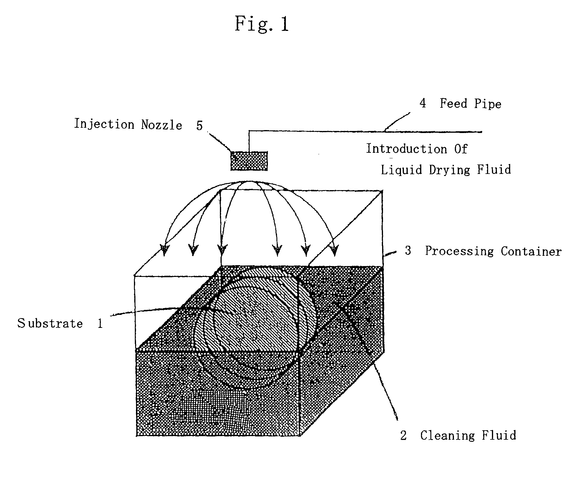
[0023]When the method for drying substrates of the first aspect is employed, the method houses substrates within the processing container, and dries the surface of each substrate by relatively lowering the fluid face of cleaning fluid within the processing container with respect to the substrate and by introducing the drying fluid within the processing container. During this operation, the method introduces drying fluid under a liquid condition within the processing container, and injects the introduced drying fluid onto the fluid face of the cleaning fluid using a
nozzle. Therefore, the drying fluid is smoothly introduced between the substrates due to the influence of
dead weight of the liquid drying fluid so that the drying fluid is supplied with higher density with respect to the density of the vapor supplying so as to improve
MARANGONI effect. Consequently, a
liquid layer of the drying fluid is generated on the cleaning fluid so that drying of the substrates with greatly little drying mark is rapidly realized using
MARANGONI effect. Further, the drying fluid is supplied in a
liquid phase condition, so that the entirety or almost all of the drying fluid is discharged with the cleaning fluid. Consequently, leakage of the drying fluid is decreased up to nearly zero so that exhaust equipment is eliminated or is simplified. As a result, a decrease in cost is realized.
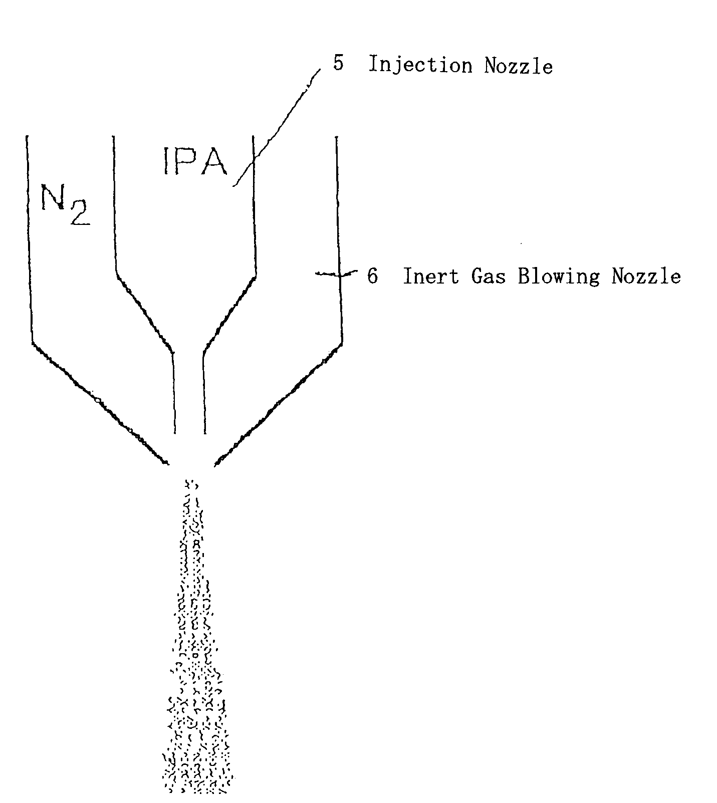
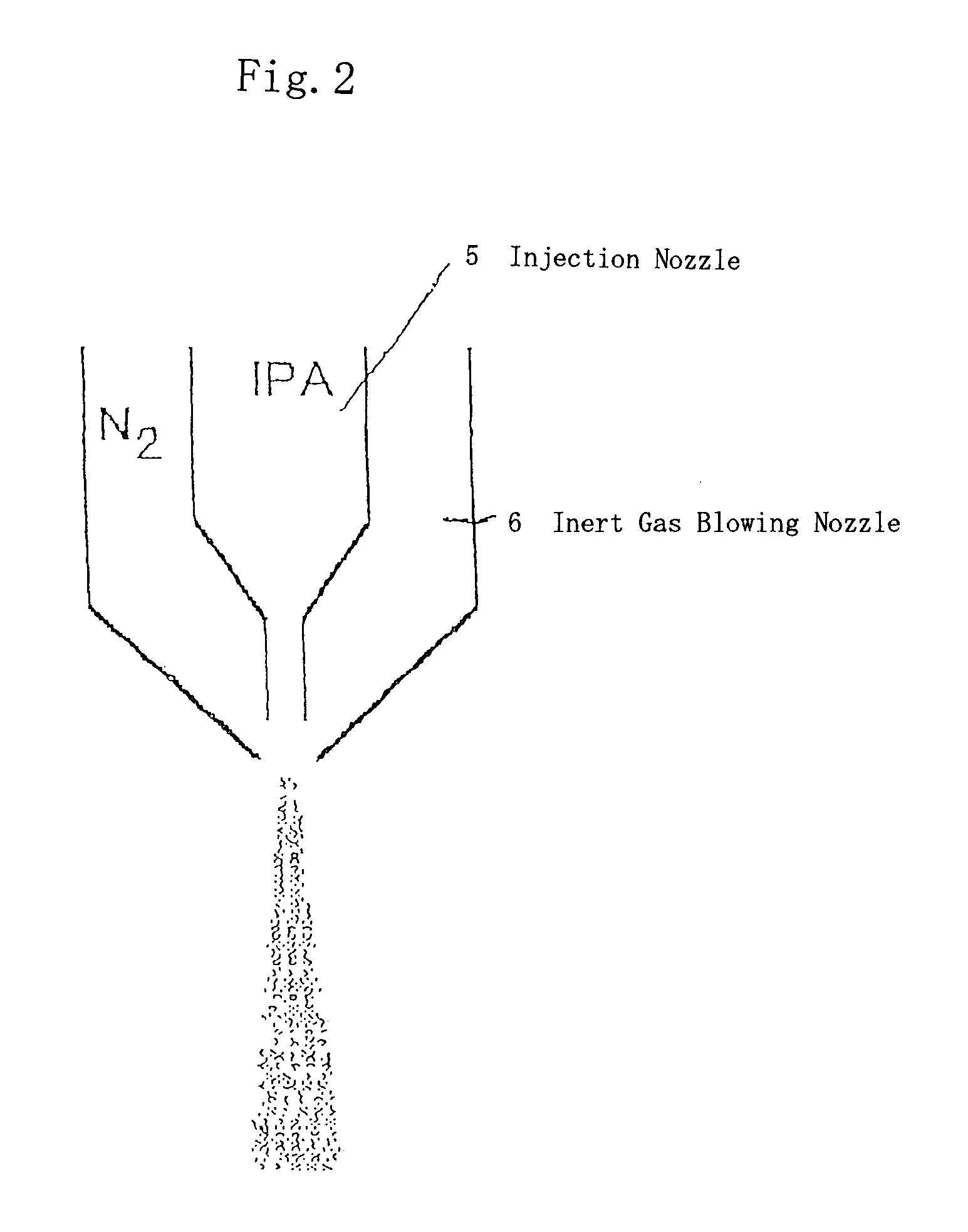
[0024]When the method for drying substrates of the second aspect is employed, the method blows
inert gas for atomizing the drying fluid. Therefore,
disadvantage is prevented from occurrence that droplet of the injected liquid drying fluid becomes too large, so that superior drying of the substrates is realized. In addition, operations and effects are realized which are similar to those of the first aspect.
[0028]Therefore, the drying fluid is smoothly introduced between the substrates due to the influence of
dead weight of the liquid drying fluid so that the drying fluid is supplied with higher density with respect to the density of the vapor supplying so as to improve
MARANGONI effect. Consequently, a
liquid layer of the drying fluid is generated on the cleaning fluid so that drying of the substrates with greatly little drying mark is rapidly realized using MARANGONI effect. Further, the drying fluid is supplied in a
liquid phase condition, so that the entirety or almost of the drying fluid is discharged with the cleaning fluid. Consequently, leakage of the drying fluid is decreased up to nearly zero so that exhaust equipment is eliminated or is simplified. As a result, decrease in cost is realized.
[0032]Therefore, the drying fluid is smoothly introduced between the substrates due to the influence of
dead weight of the liquid drying fluid so that the drying fluid is supplied with higher density with respect to the density of the vapor supplying so as to improve MARANGONI effect. Consequently, a
liquid layer of the drying fluid is generated on the cleaning fluid so that drying of the substrates with greatly little drying mark is rapidly realized using MARANGONI effect. Further, the drying fluid is supplied in a
liquid phase condition, so that the entirety or almost of the drying fluid is discharged with the cleaning fluid. Consequently, leakage of the drying fluid is decreased up to nearly zero so that exhaust equipment is eliminated or is simplified. As a result, decrease in cost is realized. Furthermore, the blowing quantity of the drying fluid from the blowing opening of the
nozzle is suppressed so that the drying fluid of proper quantity is supplied to the dipping boundary face of the substrates. Consequently, usage quantity of the drying fluid is decreased and the running cost is decreased.
[0034]Therefore, the drying fluid is smoothly introduced between the substrates due to the influence of dead weight of the liquid drying fluid so that the drying fluid is supplied with higher density with respect to the density of the vapor supplying so as to improve MARANGONI effect. Consequently, a liquid layer of the drying fluid is generated on the cleaning fluid so that drying of the substrates with greatly little drying mark is rapidly realized using MARANGONI effect. Further, the drying fluid is supplied in a liquid phase condition, so that the entirety or almost of the drying fluid is discharged with the cleaning fluid. Consequently, leakage of the drying fluid is decreased up to nearly zero so that exhaust equipment is eliminated or is simplified. As a result, decrease in cost is realized. Furthermore, the blowing quantity of the drying fluid from the blowing opening of the nozzle is suppressed so that the drying fluid of proper quantity is supplied to the dipping boundary face of the substrates. Consequently, usage quantity of the drying fluid is decreased and the running cost is decreased.
[0035]When the device for drying substrates of the ninth aspect is employed, the drying fluid supplying means comprises a first feed
pipe for supplying carrier gas to the nozzle and a second feed
pipe for supplying liquid drying fluid which is communicated to the halfway of the first feed pipe. Therefore, the blowing quantity of the drying fluid from each blowing opening is determined to be a proper quantity so that the consumption quantity of the drying fluid is decreased and the cost is decreased. In addition, operations and effects are realized which are similar to those of the eighth aspect.

