
Device and method for acoustic diagnosis and measurement by pulse electromagnetic force

a technology of electromagnetic force and acoustic diagnosis, which is applied in the direction of instruments, specific gravity measurement, and processing detected response signals, etc., can solve the problems of different limitations, shape, size, and location, and conventional methods of detecting the location of reinforcing iron rods or corrosion of reinforcing iron rods, etc., to achieve the effect of easy determination and easy determination of the location of water pipes

Inactive Publication Date: 2005-11-08
AMIC CO LTD
View PDF3 Cites 13 Cited by
  • Summary
  • Abstract
  • Description
  • Claims
  • Application Information

AI Technical Summary

Benefits of technology

[0024]In this technique, because the reinforcing iron rod is directly excited by the magnetic field pulse, a very large acoustic waveform can be obtained compared with that obtained in the conventional technique in which an ultrasonic wave generated by an ultrasonic source is reflected from the reinforcing iron rod. Furthermore, in this technique according to the present invention, unlike the conventional percussion method, the degree of corrosion, the strength of adhesion, the cover depth, and / or the diameter of the reinforcing iron rod can be diagnosed or measured non-destructively in a highly reliable fashion.
[0068]It is also possible to easily determine the location of a water pipe or a gas pipe buried in the ground.

Problems solved by technology

However, the conventional methods of detecting locations of reinforcing iron rods or corrosion of reinforcing iron rods have problems as described below.
For example, in radiography, it is needed to put a structure between the X-ray generator and the film, and thus this method has various limitations such as those on the shape, the size, and the location.
This method cannot be substantially used for tunnels, dams, or the like.
Another problem is that control is needed so as to prevent a human body from being significantly damaged by an X-ray and thus it is not easy to employ this method.
Because detection is based on the skill, it is difficult to achieve high reliability in detection.
When diagnosis of corrosion is performed using this method, corrosion cannot be easily detected unless reinforcing iron rods are so significantly corroded that a void is created.
In this method, detection of corrosion is based on the skill and thus the reliability of detection is low.
However, the concrete includes gravel and a large number of non-continuous parts created by bubbles or the like, which cause the ultrasonic wave to be attenuated or scattered and thus make it difficult to perform analysis.
However, it is needed to continuously perform measurement over a long period and it is also needed to apply an unnecessarily large load.
Thus, this technique is not suitable for detection of corrosion of a structure.
As described above, no conventional method is known which allows high-reliability non-destructive detection of the degree of corrosion of reinforcing iron rods in reinforced concrete, adhesion strength between concrete and reinforcing iron rods, or the location or the diameter of a reinforcing iron rod in concrete.
The lack of effective methods causes an error to occur in prediction of strength or life, and thus can cause an unpredictable disaster to occur.
When such a structure is used for a long period, there is a possibility that a reinforcing iron rod fractures.
However, no conventional technique is known which allows such a fracture to be detected in a non-destructive fashion.
Therefore, periodical replacement at scheduled intervals is needed, or otherwise an unpredictable disaster can occur.
However, such an apparatus is complicated and special technical knowledge is needed to handle it.
There is no technique which can be easily used to detect a precise location under ground.
Thus, in many cases, a troublesome job, such as digging up the ground, is needed to make confirmation.
However, in structures having a large size such as bridges, large bolts and nuts are used and they are fastened by very large torque.
Therefore, it is impossible to manually diagnose using a torque wrench or the like, and diagnosis is performed using a dedicated machine having a large size.
Another problem in such diagnosis is that it is necessary to close the bridge during the diagnosis.

Method used


Image

  • Device and method for acoustic diagnosis and measurement by pulse electromagnetic force
  • Device and method for acoustic diagnosis and measurement by pulse electromagnetic force
  • Device and method for acoustic diagnosis and measurement by pulse electromagnetic force

Examples


Embodiment Construction

[0099]Embodiments of the present invention are described in detail below with reference to drawings.

[0100]First, an embodiment of an acoustic diagnosis / measurement apparatus using a pulse of electromagnetic force according to the present invention and a method therefor are described.

[0101]Herein, by way of example, the structure including a conductor and a non-conductive material covering the conductor subjected to diagnosis / measurement is assumed to be a structure made of concrete reinforced with iron rods.

[0102]The apparatus of the present embodiment is capable of making diagnosis / measurement in terms of corrosion, adhesion, cover depth, and diameters of iron rods.

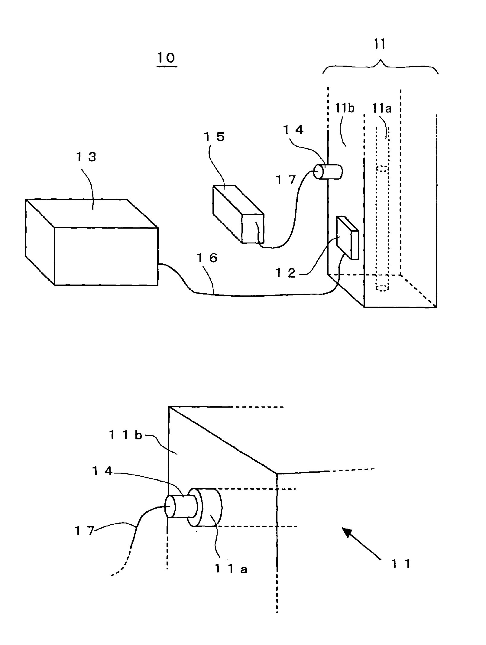
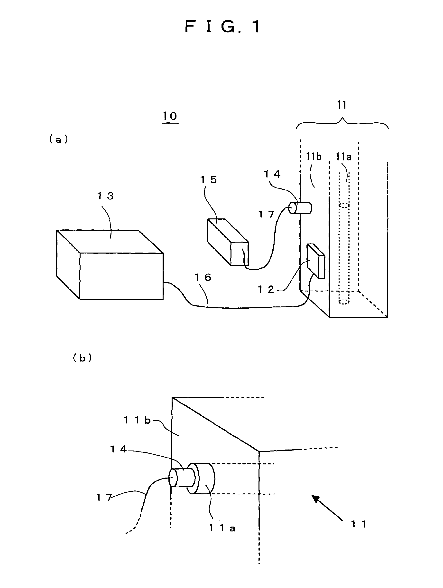
[0103]FIGS. 1(a) and 1(b) are conceptual diagrams showing the embodiment of the acoustic diagnosis / measurement apparatus using a pulse of electromagnetic force according to the present invention and the method therefor, wherein FIG. 1(a) shows a manner in which an acoustic transducer is attached to a surface of concrete,...


PUM


Abstract

The invention provides an acoustic diagnosis / measurement apparatus / method using a pulse of electromagnetic force, capable of non-destructively and precisely diagnosing or measuring corrosion, adhesion, the cover depth, and / or the diameter of a reinforcing iron rod in a structure made of reinforced concrete. A coil 12 is attached to a surface of a structure 11 including a conductor 11a and a non-conductive material 11b covering the conductor 11a. A current pulse is applied to the coil 12 thereby generating a magnetic field pulse. The magnetic field pulse causes an eddy current to be induced in the conductor 11a. The conductor 11a is oscillated by interaction between the eddy current and the magnetic field pulse. As a result, an acoustic signal is generated by the conductor 11a and the acoustic signal is converted into an eclectic signal by an acoustic transducer 14 disposed to the surface of the structure 11. The resultant electric signal is measured by a measurement unit 15 to diagnose / measure the location of the conductor 11a or the state of the structure 11.

Description

TECHNICAL FIELD[0001]The present invention relates to an acoustic diagnosis / measurement apparatus using a pulse of electromagnetic force for diagnosing / measuring a structure including a conductor and a non-conductive material covering the conductor, and a method of diagnosing / measuring such a structure, in particular, in terms of corrosion or adhesion of a reinforcing iron rod in reinforced concrete, the location of the reinforcing iron rod, the diameter of the reinforcing iron rod, presence / absence of a fracture in the reinforcing iron rod, or the location of the fracture, or in terms of the location of a water pipe buried in the ground, or in terms of whether a conductor is securely bound by a binding member.BACKGROUND ART[0002]In a structure made of reinforced concrete, such as a tunnel, a bridge, a building, a retaining wall, a dam, or a civil construction, in order to evaluate the strength or life or to determine construction procedure, it is needed to detect locations of reinf...

Claims


Application Information

Patent Timeline
IPC IPC(8): G01N17/00G01N29/44G01N29/24G01N29/46G01N33/38
CPCG01N17/006G01N29/2412G01N29/46G01N33/383G01N2291/015G01N2291/02458G01N2291/0255G01N2291/02827G01N2291/02854G01N2291/0423G01N2291/102
Inventor HASHIMOTO, MITSUOTAKANABE, MASANORI
Owner AMIC CO LTD
Learn More