Catherization system and method

a technology of catherization system and optical fiber, applied in the field of catherization system, can solve the problems of system failure, insufficient filter to catch all debris which may flow downstream, and insufficient procedure to remove substantial amounts of blockag

Inactive Publication Date: 2005-11-08
POLEO JR LOUIS A
View PDF6 Cites 60 Cited by
  • Summary
  • Abstract
  • Description
  • Claims
  • Application Information

AI Technical Summary

Benefits of technology

[0012]In yet another aspect of the invention, the hollow cylindrical tube and IR optical fibers are made of IR specific plastic to avoid splintering in a high temperature / high vacuum environment.

Problems solved by technology

This procedure does not remove substantial amounts of blockage because ultra violet radiation is too cool to melt the blockage.
While the catherization system includes a filter, the filter is not sufficient to catch all debris which may flow downstream.
Such prior systems have failed because they have not effectively removed arterial blockage from the artery walls, and have not effectively removed arterial debris from the artery once the arterial blockage has been dislodged.
In addition, such prior systems have not adequately protected the artery walls from physical or thermal injury.
Further, many of the prior art devices embody numerous parts which tend to fail or shatter in a high temperature / high vacuum environment.

Method used


Image

  • Catherization system and method
  • Catherization system and method
  • Catherization system and method

Examples


first embodiment

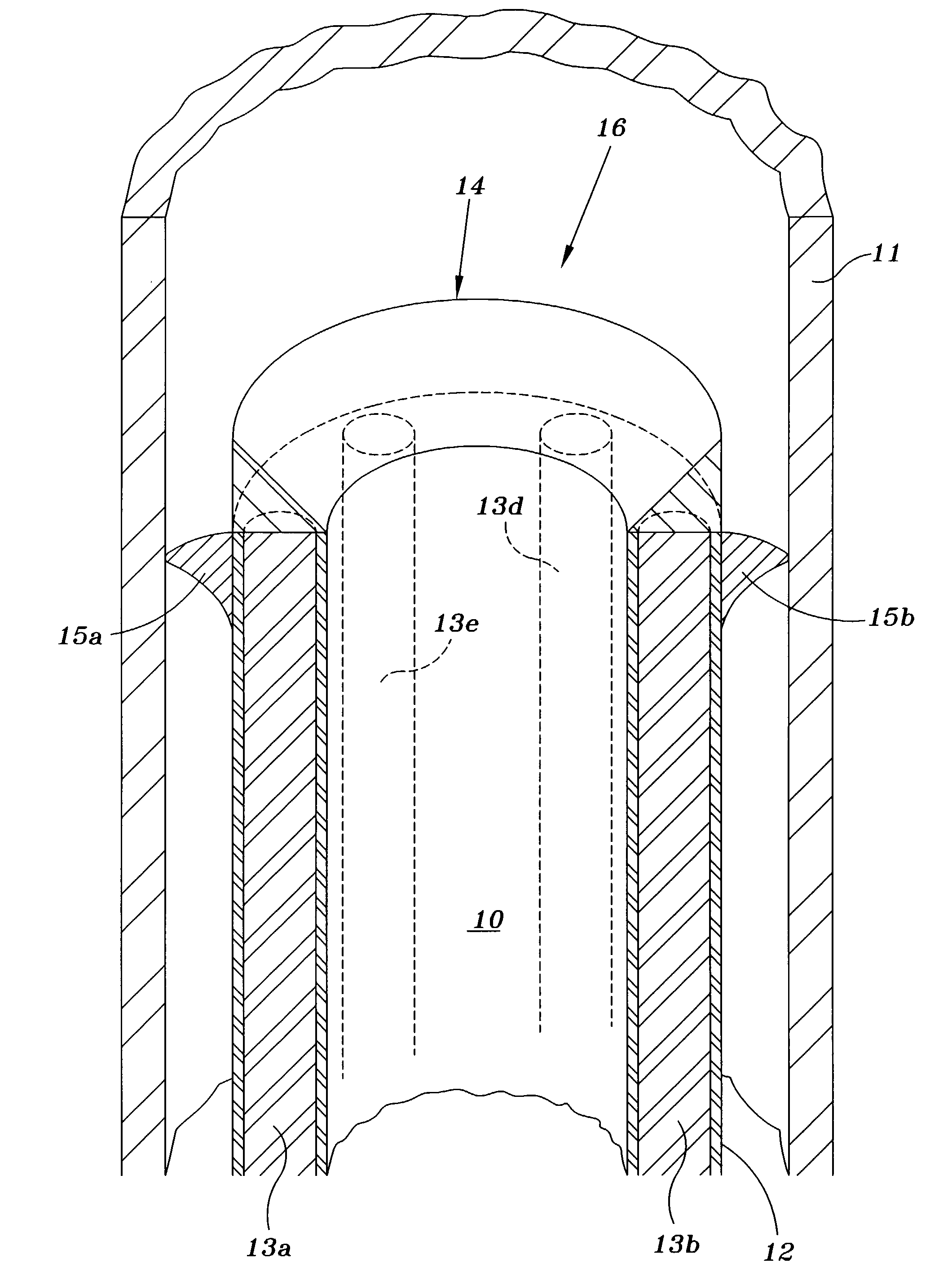
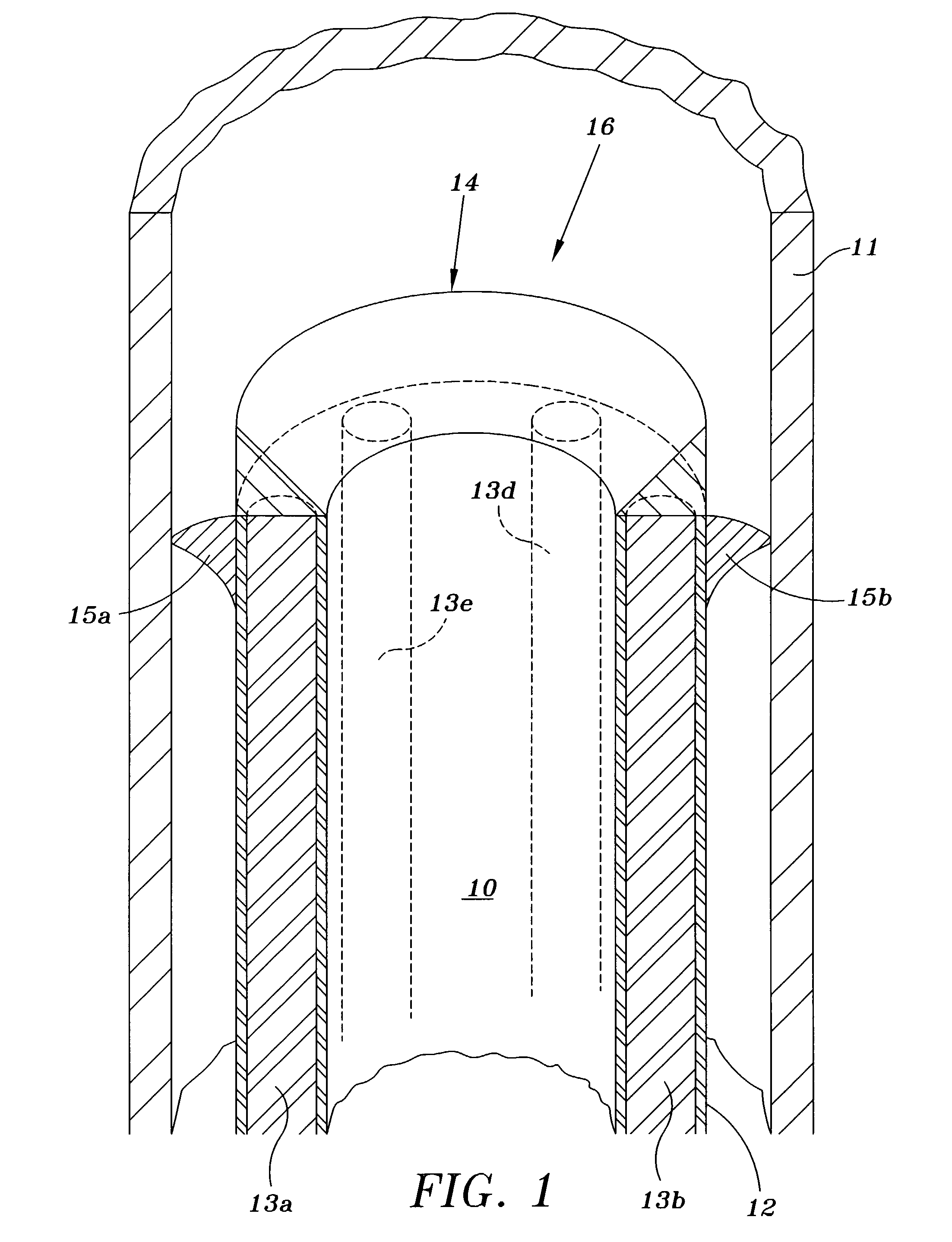
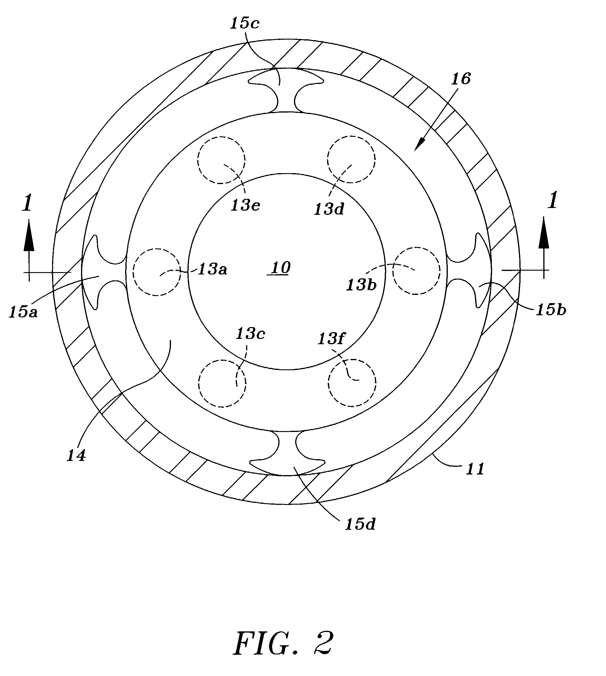
[0025]The hollow cylindrical tube 10 with outer Teflon coating 12; IR optical fibers 13a, 13b, 13d, and 13e; metal clad tip ring 14, and arterial guards 15a and 15b comprise the catherization system of the present invention.

[0026]The hollow cylindrical tube 10 with arterial guards 15a and 15b, and with pneumatically sealed IR optical fibers 13a, 13b, 13d, and 13e, may be commercially formed of a flexible polyvinal chloride (DEHP) type of plastic by any of numerous plastic product manufacturers such as PLAS-LABS of Lansing, Mich. The metal clad tip ring 14 is preferably gold, and may be manufactured commercially by any of numerous metallurgists including those generally used by hospitals.

[0027]In operation, dye is inserted into the artery 11 to pinpoint the exact location of artery blockage by X-ray. The catherization system generally referred to by reference number 16 thereafter is inserted into the artery 11, and the metal clad tip ring 14 is pushed against the artery blockage to b...

third embodiment

[0031]FIG. 4 illustrates the invention as used in conjunction with a stent. The catherization system 20 differs from the catherization system 16 of FIG. 1 only by the absence of arterial guards and Teflon coating 12, and the design of the metal clad tip ring 22. Referring to FIG. 4, a stent 21 is first inserted into the artery 11 to abut any arterial blockage previously found by use of an X-ray dye. IR optical fibers as represented by reference numbers 13a and 13b are shown to be pneumatically sealed between the inner and outer walls of the hollow cylindrical tube 10, and extend the longitudinal length of the tube to abut the lower surface of the metal clad tip ring 22. In operation, the stent 21 is pressed against the inner walls of the artery 11 through use of a water filled balloon internal to the stent. Thereafter, the catherization system 20 is advanced into the stent 21 to abut the artery blockage. A vacuum is then created within the inner walls of the hollow cylindrical tube ...


PUM


Abstract

An artery blockage removal system including a hollow plastic tube with IR optical fibers extending longitudinally between its inner and outer walls, the end of the tube having a metal clad tip ring preferably of gold abutting against the end of the IR optical fibers, and the outer surface of the hollow plastic tube having curved arterial guards molded into its outer circumference to hold the inner walls of the artery away from the hollow plastic tube and metal clad tip ring to avoid physical and thermal damage to the inner artery walls, whereby arterial blockage is removed through application of the metal clad tip ring heated by the IR optical fibers and a vacuum applied through the center of the hollow tubing.

Description

FIELD OF THE INVENTION[0001]The invention is related generally to catherization systems, and more particularly to an IR optical fiber catherization system for dislodging arterial blockage and removing resulting arterial debris through application of a vacuum without any damage occurring to artery walls.BACKGROUND OF THE INVENTION[0002]Systems for removing arterial debris are known which vary from use of lasers, heated coils, or stents for vaporizing arterial blockage, to mechanical devices such as vibrating conical sandpaper for abrading, so-called nibbler chomping pistons for biting, or rotating blades for cutting the blockage away from the artery walls.[0003]An Excimer Laser Coronary Angioplasty system and procedure offered by Spectranetics of Colorado Springs, Colo., involves the insertion into an artery of a laser catheter containing a bundle of optical fibers and a stent with a guide wire. The laser catheter is advanced in the artery until the guide wire crosses a blockage, at ...

Claims


Application Information

Patent Timeline
Patent Type & Authority Patents(United States)
IPC IPC(8): A61B18/20A61B18/24A61B18/28
CPCA61B18/245A61B18/28
Inventor POLEO, JR., LOUIS A.
Owner POLEO JR LOUIS A
Why Eureka
Try Eureka