
Analog to digital converter with voltage comparators that compare a reference voltage with voltages at connection points on a resistor ladder

a voltage comparator and analog-to-digital converter technology, applied in the field of analog-to-digital converters, can solve the problems of lack of voltage comparator gain, distinctly imperfect characteristics, and decrease in the input voltage of voltage comparators, so as to achieve low cost, low cost, and high-speed operation.

Inactive Publication Date: 2005-11-08
RENESAS ELECTRONICS CORP
View PDF8 Cites 21 Cited by
  • Summary
  • Abstract
  • Description
  • Claims
  • Application Information

AI Technical Summary

Benefits of technology

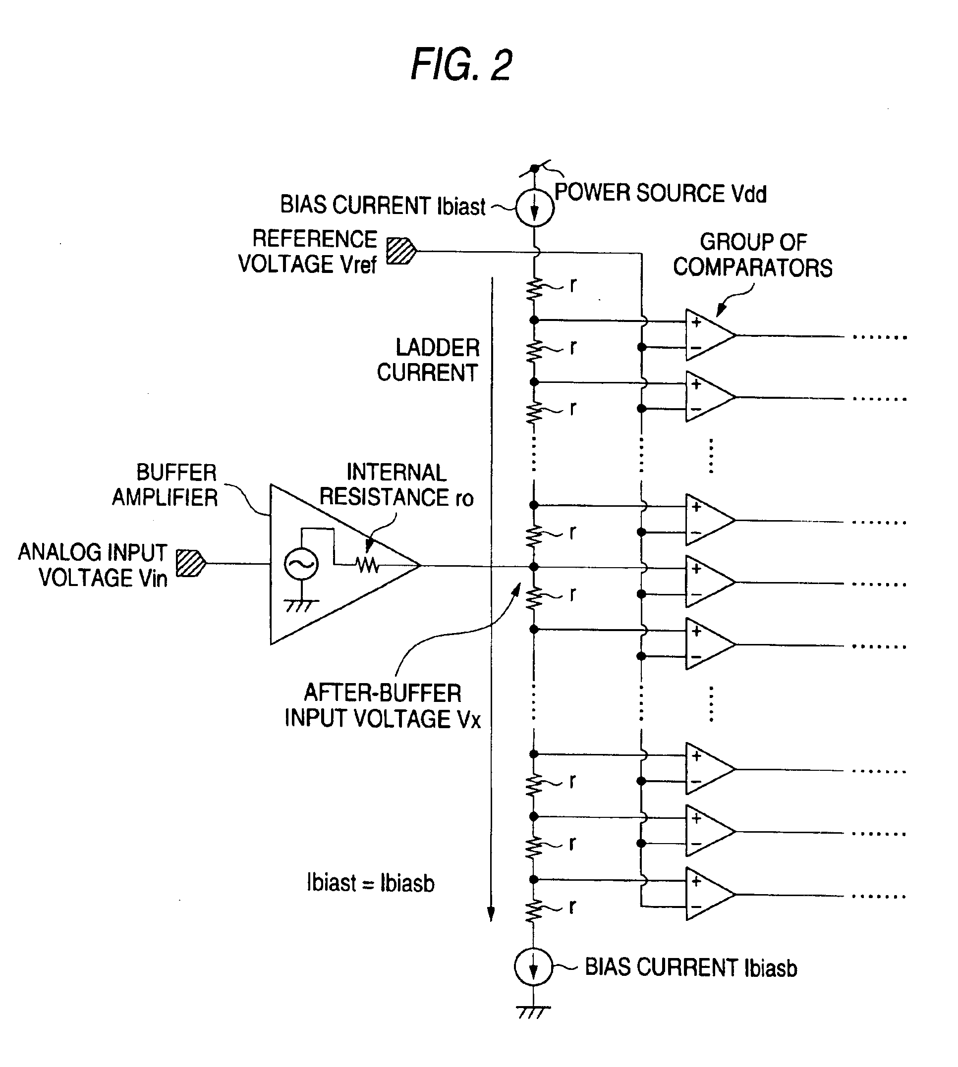
[0013]The present invention, therefore, provides an AD converter which does not use a buffer for receiving the input signals, or which uses a buffer having loose requirements concerning the range of input signals and output impedance. The invention, further, provides an AD converter which consumes less electric power, features a small circuit scale, and realizes a high-speed operation.

Problems solved by technology

In this portion, a difference in the input voltage of the voltage comparator decreases, and there distinctly appears imperfectness in the characteristics, such as lack of gain of the voltage comparator and offset.
If the voltage comparators are not designed for each of the input reference voltages Vrefi, the operation range must be broadened so as to permit the operation over the whole range of input voltages, resulting in an increase in the scale of the circuit and an increase in the consumption of electric power.
When the output impedance is not sufficiently low, further, there occurs distortion due to dependency of the output impedance upon the output voltage, though the distortion due to the buffer itself may be small.
Further, the AD converter of the literature 2 has a problem concerning the range of the analog input signals.
In the AD converter of the above literature, however, it is difficult to set the input voltage to be one-half the power source voltage due to its constitution, and the input voltage must be set being deviated toward either the power source side or the ground side.
Therefore, limitation is imposed on the maximum amplitude of the input signals, which is disadvantageous from the standpoint of signal to noise ratio (S / N ratio).
An increase in the amplitude causes a distortion.

Method used


Image

  • Analog to digital converter with voltage comparators that compare a reference voltage with voltages at connection points on a resistor ladder
  • Analog to digital converter with voltage comparators that compare a reference voltage with voltages at connection points on a resistor ladder
  • Analog to digital converter with voltage comparators that compare a reference voltage with voltages at connection points on a resistor ladder

Examples


Embodiment Construction

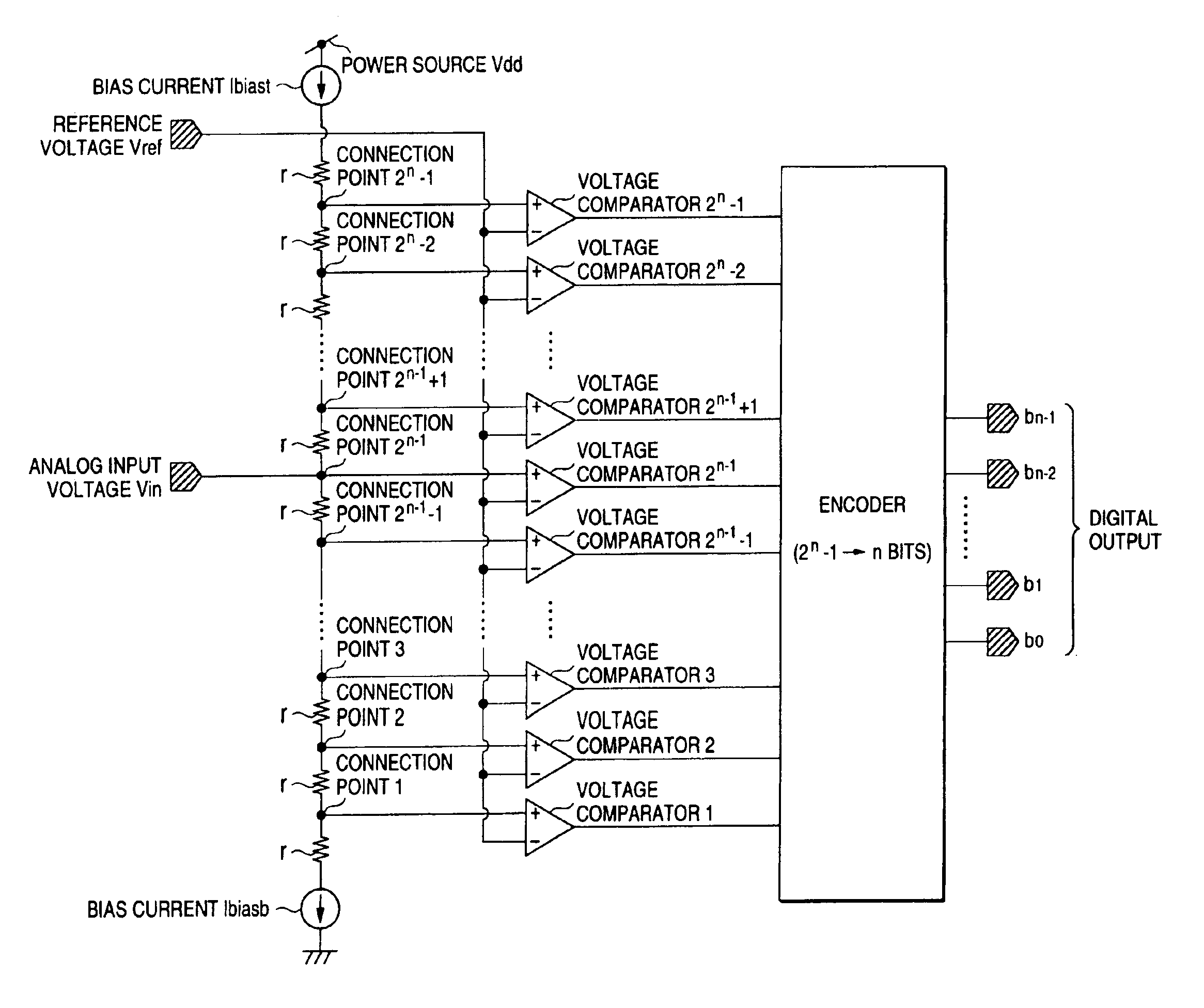
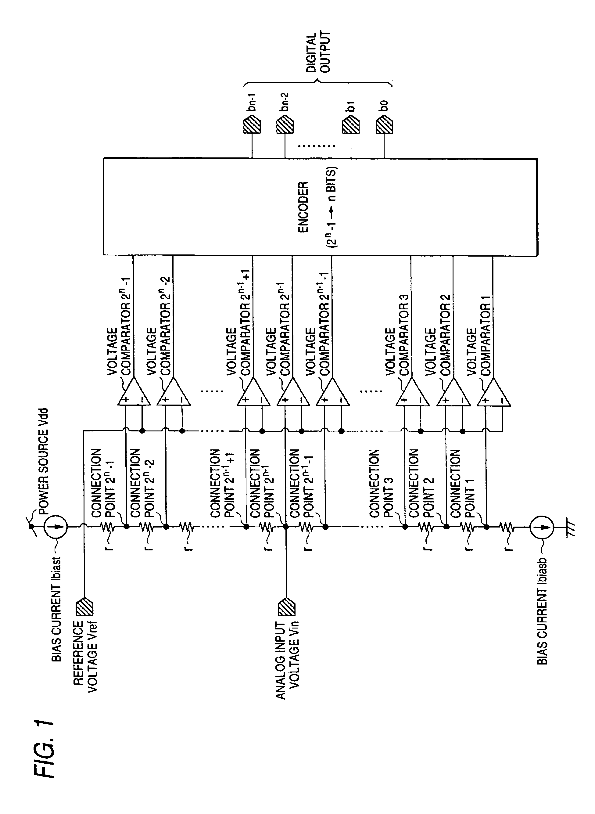
[0029]FIG. 1 is a circuit diagram illustrating an embodiment of a flash-type AD converter according to the invention. Though there is no particular limitation, the circuit elements and the circuit blocks are formed on a semiconductor substrate as represented by a single crystalline silicon by a known technology for producing CMOS semiconductor integrated circuits.

[0030]In this embodiment, when the AD converter has a resolution of n bits, there is provided a resistor ladder having 2n resistors having a resistance r. The letter “r” represents the resistance as described above and further represents a unit of resistance element that constitutes the resistor ladder. Though there is no particular limitation, a blow-out type (source type) constant-current circuit (first current circuit) constituted by a current mirror circuit is provided at an upper end (high potential side) of the resistor ladder, and a suction type (sink type) constant-current circuit (second current circuit) constitute...


PUM


Abstract

An AD converter which uses no buffer for receiving the input signals or uses the buffer having relaxed requirements concerning the range of input signals and the output impedance. Voltage at the connection points of a resistor ladder in which a plurality of resistor elements are connected in series, are compared with a reference voltage by a plurality of voltage comparators, a first current circuit is provided on the high potential side of the resistor ladder, a second current circuit is provided on the low potential side thereof, and analog input voltages are fed by providing an input terminal at any place of the resistor ladder except both ends thereof.

Description

BACKGROUND OF THE INVENTION[0001]1. Field of the Invention[0002]This invention relates to an AD (analog to digital) converter. More specifically, the invention relates to technology that can be effectively utilized for a parallel comparison (flash) type analog to digital converter.[0003]2. Description of the Related Art[0004]An HDD (hard disk drive) and a DVD (digital versatile disk) have now been widely used as a data storage or as a dynamic image medium in personal computers. Such disk data storage systems can roughly be divided into those based on analog signal processing and those based on digital signal processing for reading out the signals recorded in the disk. The latter system reproduces, based on the digital signal processing, the initial data sequence from the signals that are taken in by using a magnetic head or an optical pickup while removing such effects as interference among the codes.[0005]Therefore, the signals read out from the disk are, first, converted into digi...

Claims


Application Information

Patent Timeline
IPC IPC(8): H03M1/36
CPCH03M1/363
Inventor OTSUKA, MASANORIYAMAKIDO, KAZUOYAMAMOTO, ETSUJISANO, SHINYA
Owner RENESAS ELECTRONICS CORP
Learn More