Display driving apparatus with compensating current and liquid crystal display apparatus using the same

a technology of liquid crystal display and current compensation, which is applied in the direction of electric digital data processing, instruments, computing, etc., can solve the problems of special demand for miniaturization and achieve the effect of accurate gradation display voltage and low electric power consumption

Inactive Publication Date: 2005-11-08
SHENZHEN TOREY MICROELECTRONIC TECH CO LTD
View PDF8 Cites 15 Cited by
  • Summary
  • Abstract
  • Description
  • Claims
  • Application Information

AI Technical Summary

Benefits of technology

[0030]The present invention has an object of providing a liquid crystal display apparatus capable of generating, with low electric power co

Problems solved by technology

The reference voltage generating circuit and the output circuit occupy a large area in the gradation display circuit, and consume a large electric power.
To provide the output circuit 2

Method used


Image

  • Display driving apparatus with compensating current and liquid crystal display apparatus using the same
  • Display driving apparatus with compensating current and liquid crystal display apparatus using the same
  • Display driving apparatus with compensating current and liquid crystal display apparatus using the same

Examples


Embodiment Construction

[0060]An embodiment of the present invention is described below.

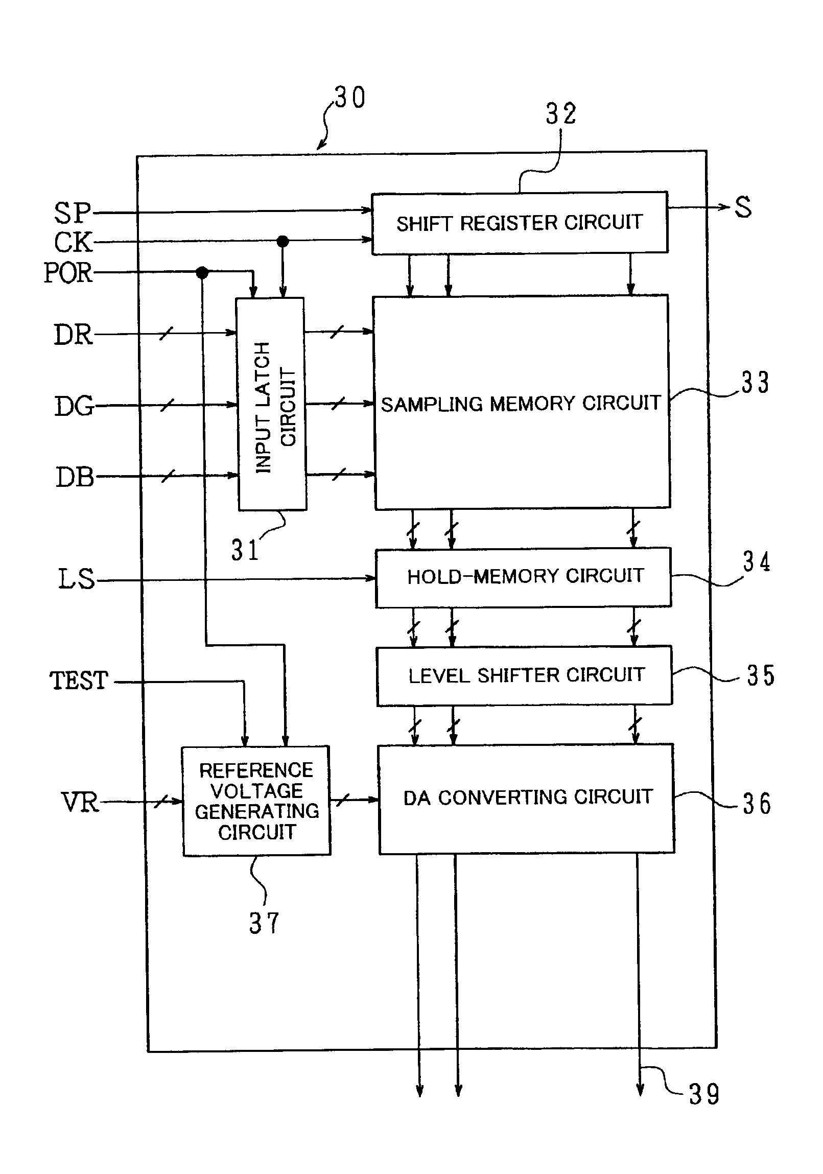
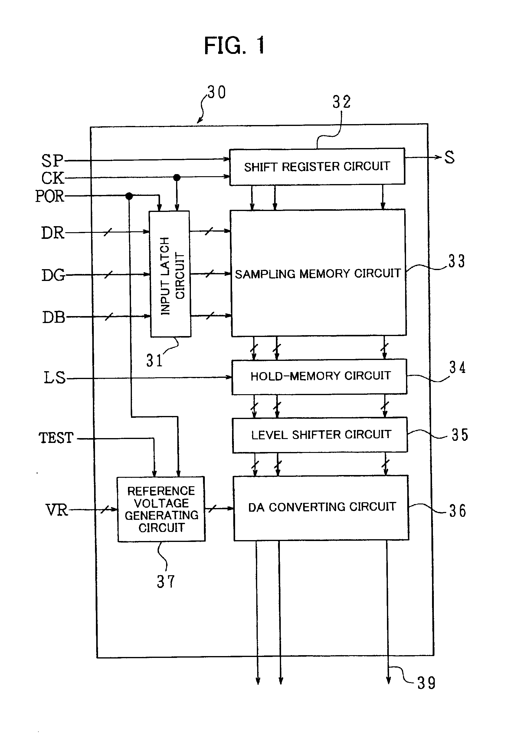
[0061]FIG. 1 is a block diagram illustrating a source driver 30 that is a display driving apparatus of the embodiment of the present invention. The source driver 30 is used as a source driver SD shown in previously discussed FIG. 12, while a liquid crystal display apparatus has a similar overall arrangement to that of a liquid crystal display apparatus of FIG. 12, except the source driver 30. A liquid crystal panel 2 has an arrangement shown in FIG. 13, and liquid crystal driving waveforms shown in FIGS. 14 and 15. Therefore, their explanation is omitted here.

[0062]The source driver 30 is provided with an input latch circuit 31, a shift register circuit 32, a sampling memory circuit 33, a hold-memory circuit 34, a level shifter circuit 35, a DA converting circuit 36, and a reference voltage generating circuit 37. The input latch circuit 31 latches respective digital display data DR, DG, and DB (for example, each of them...


PUM


Abstract

In a display driving apparatus of the present invention and a liquid display apparatus using the same, a DC current is supplied to a reference voltage generating circuit from both ends of a resistance of the resistance divided circuit, via a bypass circuit, which is a bypass other than a route from a power source. This arrangement allows the reference voltage generating circuit itself to compensate current supply ability of a reference voltage supplied from the power source, even if an output circuit is omitted from the arrangement, thereby preventing a waveform of a gradation display voltage from having non-sharp rising and falling edges, or preventing variation in voltage due to charging and discharging of a pixel capacitor. This ensures an accurate gradation display voltage.

Description

FIELD OF THE INVENTION[0001]The present invention relates to a display driving apparatus for driving a liquid crystal panel (liquid crystal display section) and the like, and to a liquid crystal display apparatus including the display driving apparatus and the liquid crystal panel, especially to a method that realizes miniaturization and low electric power consumption of a circuit.BACKGROUND OF THE INVENTION[0002]FIG. 12 is a block diagram schematically showing a liquid crystal display apparatus 1 of the TFT (Thin Film Transistor) active matrix, which is a typical liquid crystal display apparatus. The liquid crystal display apparatus 1 is basically provided with a liquid crystal panel 2 and a liquid crystal driving apparatus for driving the liquid crystal panel 2. The liquid crystal panel 2, which is a liquid crystal panel of the TFT type, is provided with liquid crystal display elements (not shown) and opposite electrode (common electrode) 3.[0003]On the other hand, the liquid crys...

Claims


Application Information

Patent Timeline
IPC IPC(8): G09G3/36G09G3/20G02F1/133
CPCG09G3/2011G09G3/3688G09G3/3696G09G2330/12G09G3/36
Inventor YANO, TAKESHIKAJIHARA, NORIYUKIORISAKA, YUKIHISA
Owner SHENZHEN TOREY MICROELECTRONIC TECH CO LTD
Why Eureka
Try Eureka