EMI shielded chassis for electrical circuitry

a technology of electrical circuitry and enclosure, which is applied in the direction of electrical apparatus casings/cabinets/drawers, casings/cabinets/drawers details, coupling device connections, etc., can solve the problems of electrostatic discharge damage of electronic components, inability to reliably ground portions of digital circuitry within the enclosure, and inability to reliably ground electrical equipment. to achieve the effect of improving serviceability

Inactive Publication Date: 2005-11-08
MCDATA SERVICES CORP
View PDF3 Cites 29 Cited by
  • Summary
  • Abstract
  • Description
  • Claims
  • Application Information

AI Technical Summary

Benefits of technology

[0010]Alignment features forming male prongs and female receptors permit the cabinetry to be aligned along the midplane and reassembled, this is a repeatable feature that enhances serviceability. A gasket seals this midline connection to suppress EMI. Captured screws, sm

Problems solved by technology

If this noise is allowed to exit the chassis enclosure or cabinetry it will cause electromagnetic interference (EMI) with other nearby electrical equipment.
Accommodating these “EMI holes” represents a continuing challenge for enclosure designers.
In addition, when the chassis enclosure is open for mainten

Method used


Image

  • EMI shielded chassis for electrical circuitry
  • EMI shielded chassis for electrical circuitry
  • EMI shielded chassis for electrical circuitry

Examples


Embodiment Construction

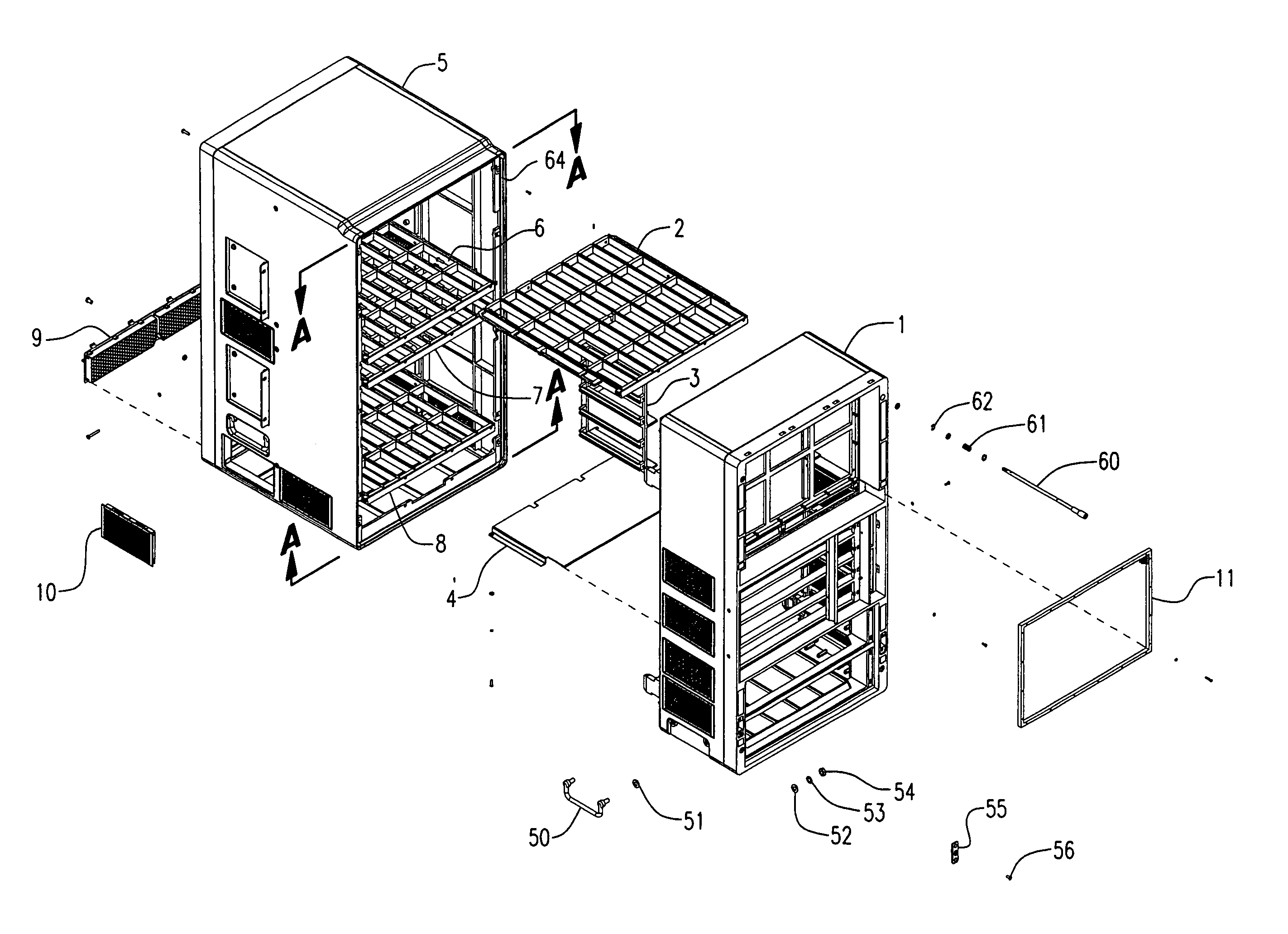
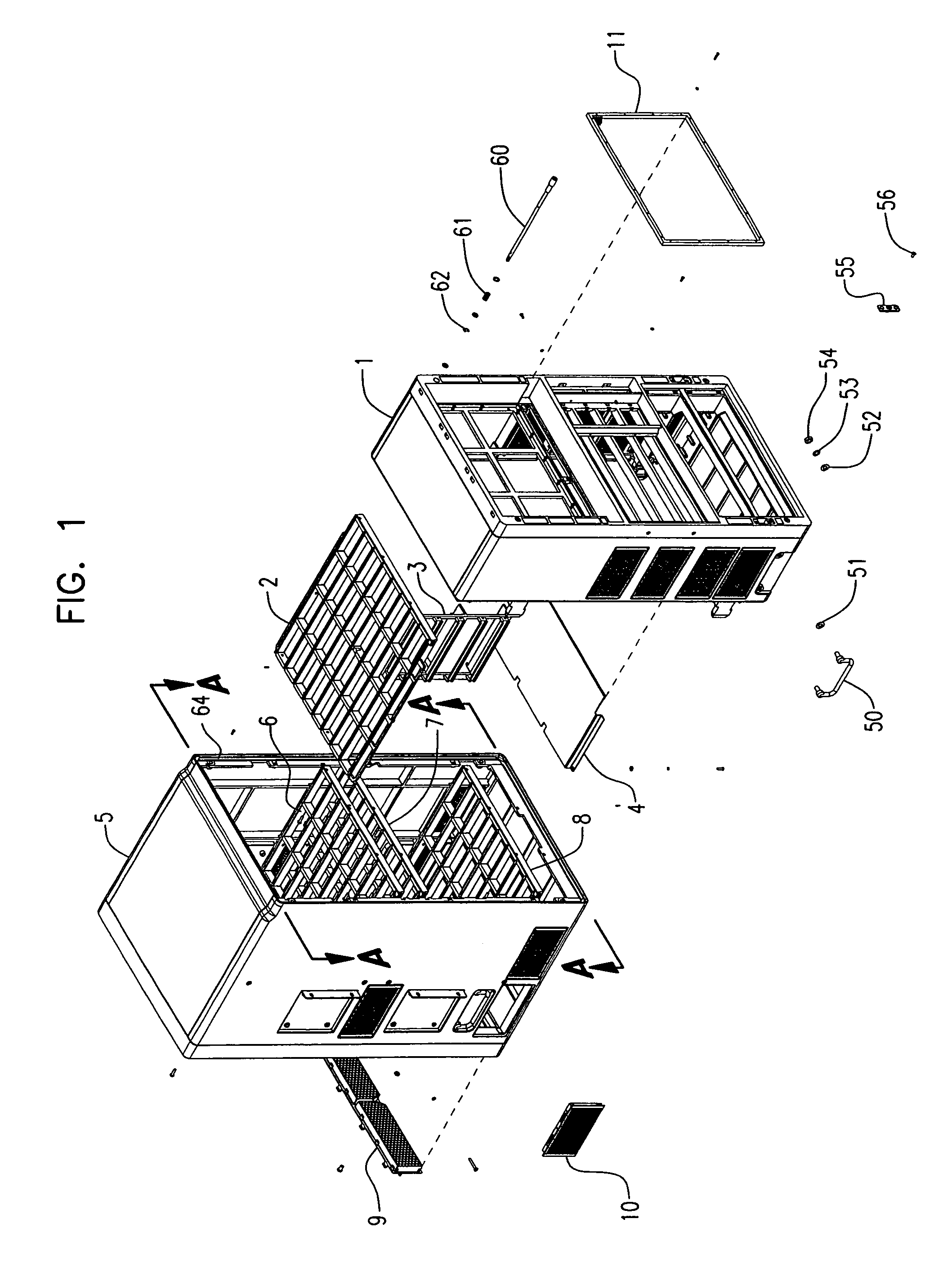
[0019]FIG. 1 is a perspective view of the overall enclosure seen from above. The drawing shows the front section 5 and the rear section 1, as well as related attached components. These components form many of the supporting structures attaching “replaceable” components, for example the front PCB edge slot cage panel 2 can be inserted into the front section 5 and positioned as depicted by PCB edge slot cage panel 6. Complementary edge slot cage panels such as panel 7 and panel 8 cooperate to retain and position vertically oriented “replaceable” printed circuit board (PCB) modules in the front section 5. In a similar fashion sets of edge card panels typified by panel 3 can be placed into the rear section 1 to retain and position horizontally orientated “replaceable” PCB modules. A midplane not shown for clarity is positioned where the front section 5 and rear section 1 mate along the plane A-A, FIG. 1, forming a complete chassis enclosure assembly. A small number (for example 4) of ca...


PUM


Abstract

An enclosure for computer-based telephone switching equipment that suppresses the radiation of electromagnetic interference through the use of multiple overlapping seals and apertures.

Description

FIELD OF THE INVENTION[0001]The present invention relates generally to electromagnetically shielded plastic chassis enclosures for use with electronic equipment such as a telecommunication switch.BACKGROUND OF THE INVENTION[0002]Modern digital circuitry operates at very high clock speeds to process data and other signals. The rapid rise times which characterize modern digital equipment gives rise to a substantial amount of broadband radio frequency radiation. If this noise is allowed to exit the chassis enclosure or cabinetry it will cause electromagnetic interference (EMI) with other nearby electrical equipment. In general, modern digital equipment is designed to comply with EMI radiation specifications that have been adopted by industry to ensure reliable operation of digital equipment. Although a complete Faraday type enclosure is the most desirable form of electromagnetic shielding for an enclosure, practical devices require both input and output ports to interact with their env...

Claims


Application Information

Patent Timeline
IPC IPC(8): H05K9/00H04Q1/02H05K7/14
CPCH05K7/1425H05K9/0067H04Q1/035H04Q1/116H04Q1/025H04Q2201/10H04Q2201/14
Inventor CARULLO, THOMAS J.WILLERS, ARTHUR G.GOODENOUGH, RYAN K.
Owner MCDATA SERVICES CORP
Why Eureka
Try Eureka