Power converter with an inductor input and switched capacitor outputs

a power converter and inductor technology, applied in the direction of electric variable regulation, process and machine control, instruments, etc., can solve the problems of large step change in input current that is difficult to filter, and is not optimum for most applications with low voltage outputs, so as to expand the control range

Inactive Publication Date: 2005-11-08
HERBERT EDWARD
View PDF4 Cites 42 Cited by
  • Summary
  • Abstract
  • Description
  • Claims
  • Application Information

AI Technical Summary

Benefits of technology

[0004]The power converter of this invention uses an inductor input but has the characteristics of a buck converter. In the basic power converter circuit, control can be maintained over a two to one change of input voltage, and other embodiments of the invention expand the control range.

Problems solved by technology

It has the disadvantage that the input is the switching stage so there are large step changes in the input current that are difficult to filter.
The familiar “Boost converter” uses an inductor in its input that provides a smoother current wave form, but it is most useful for step up applications and is not optimum for most applications having low voltage outputs.

Method used


Image

  • Power converter with an inductor input and switched capacitor outputs
  • Power converter with an inductor input and switched capacitor outputs
  • Power converter with an inductor input and switched capacitor outputs

Examples


Embodiment Construction

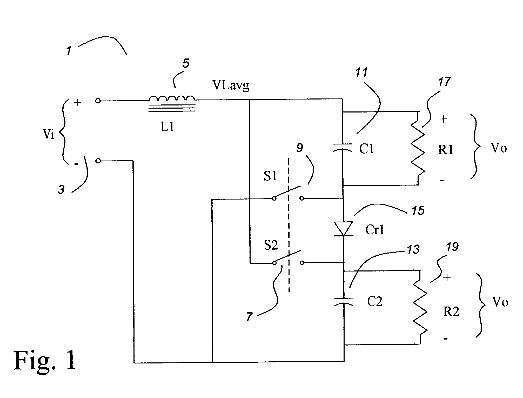
[0015]FIG. 1 shows a power converter 1 of this invention connected to an input voltage source 3 Vi. The input voltage source 3 Vi is connected to a first terminal of an inductor 5 L1. The second terminal of the inductor 5 L1 is connected to the first terminal of a switch 7 S2, and the first terminal of a capacitor 11 C1. The second terminal of the capacitor 11 C1 is connected to the first terminal of a switch 9 S1 and the anode of a rectifier 15 Cr1. The cathode of the rectifier 15 Cr1 is connected to the first terminal of a second capacitor 13 C2 and the second terminal of the switch 7 S2. The second terminal of the switch 9 S1 and the second terminal of the second capacitor 13 C2 are connected to the return of the input voltage source 3 Vi, as more particularly shown in the schematic diagram, FIG. 1. If the input power source 3 Vi is of opposite polarity, the rectifier polarity is reversed.

[0016]Switches 9 S1 and 7 S2 preferably are operated synchronously, that is, they are both o...


PUM


Abstract

A power converter circuit has an inductor input and switching means to put a pair of capacitors alternately in series or in parallel. By pulse width modulating between the states, the voltage on the capacitors can be controlled over a two to one variation of the input voltage. A pair of transformer isolated power converter sub-circuits can be connected to the capacitors, and their outputs can be combined to provide a single controlled output voltage.

Description

[0001]This application is a continuation in part of a provisional patent application of the same name, Ser. No. 60 / 316,402 filed 4 Sep., 2001. Priority to that date is claimed.BACKGROUND OF THE INVENTION[0002]This invention relates to DC—DC power converters, and in particular to power converters which regulate the output voltage.[0003]The familiar “Buck converter” is used frequently in power converter circuits. It has the disadvantage that the input is the switching stage so there are large step changes in the input current that are difficult to filter. The familiar “Boost converter” uses an inductor in its input that provides a smoother current wave form, but it is most useful for step up applications and is not optimum for most applications having low voltage outputs.SUMMARY OF THE INVENTION[0004]The power converter of this invention uses an inductor input but has the characteristics of a buck converter. In the basic power converter circuit, control can be maintained over a two to...

Claims


Application Information

Patent Timeline
Patent Type & Authority Patents(United States)
IPC IPC(8): H02M5/00H02M5/42H02M3/335H02M3/24H02M3/07H02M3/158
CPCH02M3/07H02M3/158H02M2001/007H02M2001/009H02M1/007H02M1/009
Inventor HERBERT, EDWARD
Owner HERBERT EDWARD
Why Eureka
Try Eureka