Satellite broadcasting receiving converter for receiving radio waves from plurality of satellites

a technology of satellites and receivers, applied in the direction of waveguide horns, wireless communication, wireless commuication services, etc., can solve the problems of inevitably necessary to use a large-sized reflector, time-consuming and cumbersome steps for connecting coaxial cables, and increase manufacturing costs, so as to achieve the effect of reducing manufacturing costs

Inactive Publication Date: 2005-11-08
ALPS ALPINE CO LTD
View PDF18 Cites 2 Cited by
  • Summary
  • Abstract
  • Description
  • Claims
  • Application Information

AI Technical Summary

Benefits of technology

[0012]The present invention has been made in view of such circumstances of the related art and it is an object of the present invention to provide a satellite broadcasting receiving converter which can reduce the manufacturing cost and, at the same time, can provide versatility.
[0014]Due to such a constitution, by overlapping the first printed circuit board and the second printed circuit board, the oscillation signal line and the intermediate frequency signal line can be made to cross each other while holding the grounding and hence, a coaxial cable which necessitates time-consuming and cumbersome operation in connection can be eliminated so that the manufacturing cost of the satellite broadcasting receiving converter can be reduced.
[0017]Further, in the above-mentioned constitution, although the first printed circuit board and the second printed circuit board may be formed of the same material, it is preferable that the second printed circuit board is formed of a material which has a Q value lower than that of a material of the first printed circuit board in view of achieving the reduction of a total cost of the printed circuit boards.
[0019]Due to such a constitution, when the radio waves transmitted from a plurality of neighboring satellites enter the openings of respective waveguides after being reflected on the reflector, since the phase of the radio waves which pass the waterproof cover are delayed by a correction part, it is possible to make adjustments such that radiation patterns of radio waves which are incident on the respective waveguides are reflected on a common portion of the reflector so that the required reflector can be miniaturized. Further, since the waveguides having the same structure as waveguides for one satellite are used, the manufacturing cost can be reduced. Still further, it is sufficient to change the waterproof cover in response to the degree of elongation of the satellites which are subjected to reception and hence, the satellite broadcasting receiving converter which can provide versatility can be realized.

Problems solved by technology

However, it is necessary to provide the coaxial cables in addition to the printed circuit board and the coaxial cables must be soldered to the signal lines after projecting the coaxial cables from the back surface to the front surface of the printed circuit board and hence, the step for connecting the coaxial cables is time-consuming and cumbersome and it gives rise to a problem that the manufacturing cost is pushed up.
However, since the opening end faces of two waveguides which are arranged in parallel are positioned within the same plane, when the radio waves transmitted from two satellites having given degree of elongation enter respective waveguides after being reflected on a common reflector, portions of the reflector which reflect only the radio waves transmitted from one satellite are increased thus giving rise to a problem that it is inevitably necessary to use a large-sized reflector.
However, since a mold for diecasting which has a complicated structure and is expensive is necessary for integrally forming two waveguides and hence, there arises a problem that the manufacturing cost of the satellite broadcasting receiving converter is pushed up.
Further, it is necessary to change the inclination angles of two waveguides corresponding to the degree of elongation of the satellites which are subjected to signal reception so that there has been a problem that the latter type cannot provide versatility.

Method used


Image

  • Satellite broadcasting receiving converter for receiving radio waves from plurality of satellites
  • Satellite broadcasting receiving converter for receiving radio waves from plurality of satellites
  • Satellite broadcasting receiving converter for receiving radio waves from plurality of satellites

Examples


Embodiment Construction

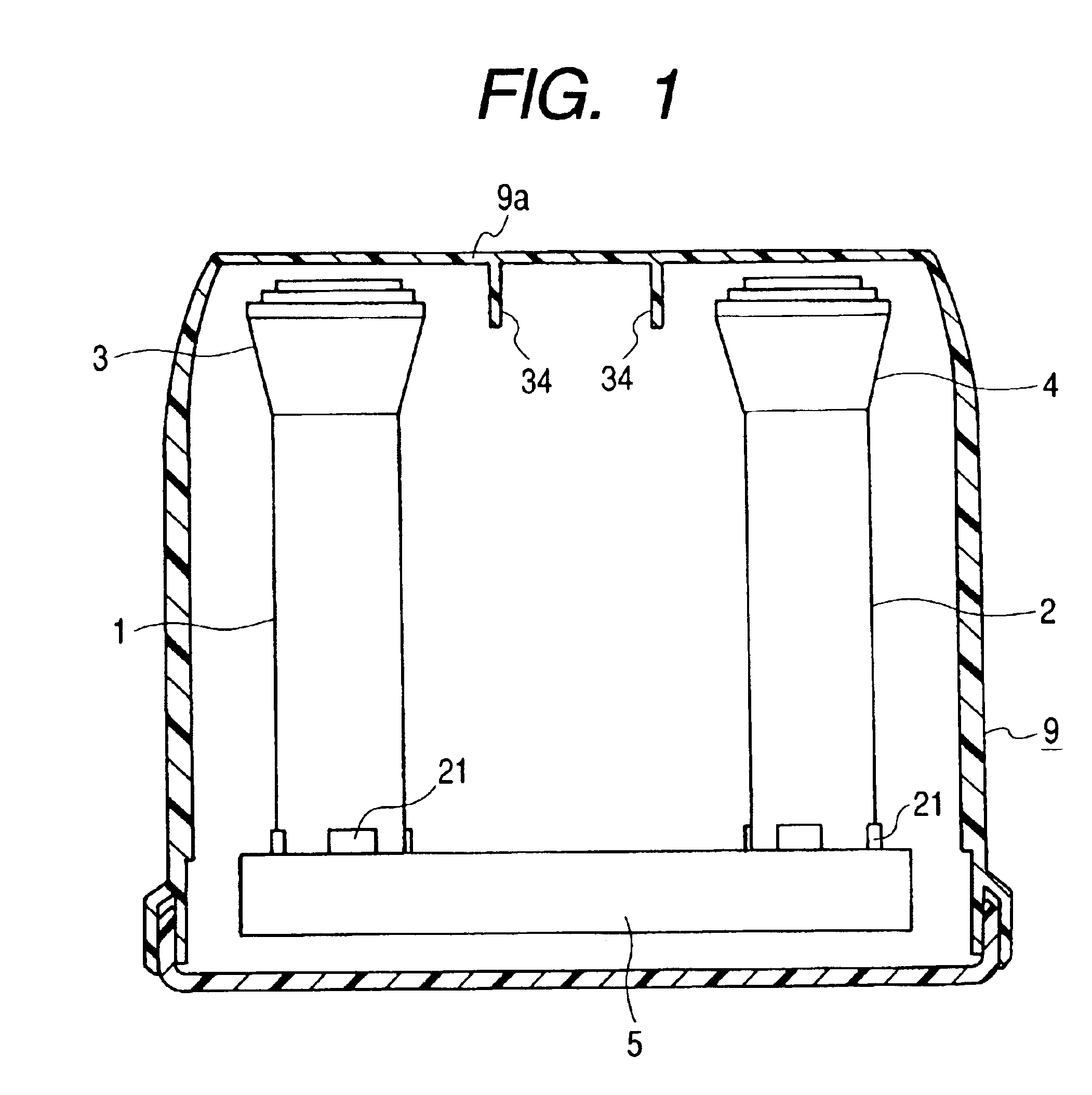
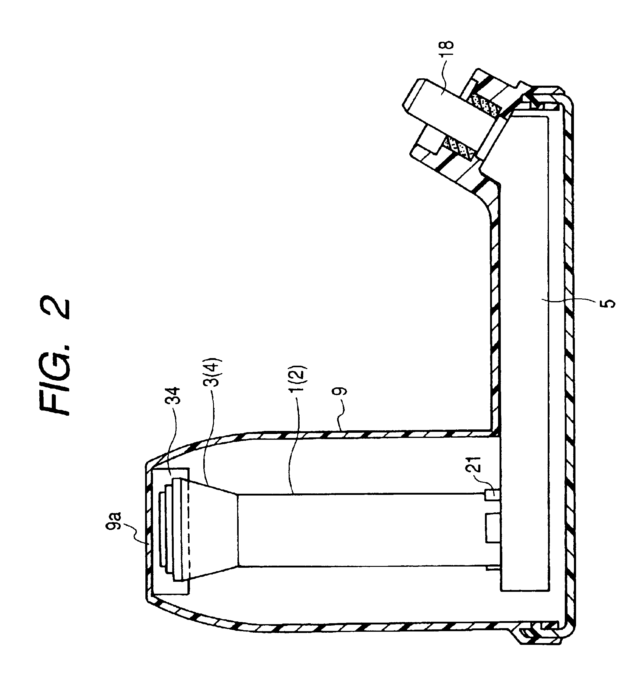
[0043]A preferred embodiment of the present invention is explained hereinafter in conjunction with attached drawings. In the drawings, FIG. 1 is a cross-sectional view of a satellite broadcasting receiving converter according to an embodiment of the present invention, FIG. 2 is a cross-sectional view of the satellite broadcasting receiving converter as viewed from a different direction, FIG. 3 is a perspective view of waveguides, FIG. 4 is a front view of the waveguide, FIG. 5 is a perspective view of a dielectric feeder, FIG. 6 is a front view of the dielectric feeder, FIG. 7 is an explanatory view showing the dielectric feeder in an exploded manner, FIG. 8 is an explanatory view showing a state in which the dielectric feeder is mounted on the waveguide, FIG. 9 is an explanatory view showing the difference between two dielectric feeders, FIG. 10 is a perspective view showing a shield case, a printed circuit board and a short cap in an exploded manner, FIG. 11 is a back view of the ...


PUM


Abstract

First and second waveguides which have respective axes thereof arranged parallel to each other are respectively held by dielectric feeders. A projection wall or a thick wall is formed as a correction part on a front surface of a waterproof cover which covers radiation parts of the dielectric feeders. Due to such a constitution, when radio waves transmitted from neighboring first and second satellites are converged by a reflector and are incident on the inside of respective waveguides, it is possible to delay a phase of radio waves which pass the waterproof cover by the correction part (projection wall or thick wall) so that it is possible to adjust such that radiation patterns of radio waves which are incident on the respective waveguides are reflected on a common portion of the reflector whereby the required reflector can be miniaturized.

Description

BACKGROUND OF THE INVENTION[0001]1. Field of the Invention[0002]The present invention relates to a satellite broadcasting receiving converter which can receive radio waves transmitted from a plurality of neighboring satellites.[0003]2. Description of the Related Art[0004]In receiving radio waves from a plurality of neighboring satellites, that is, when satellite broadcasting signals having leftward circularly polarization and rightward circularly polarization are respectively transmitted from two satellites and these satellite broadcasting signals are inputted to separate feed horns and waveguides and received by one LNB, for example, it is necessary to perform frequency conversion of the leftward circularly polarized signal and the rightward circularly polarized signal which are picked up by the waveguides into intermediate frequency bands which are different from each other. In this case, the leftward circularly polarized signal and the rightward circularly polarized signal transm...

Claims


Application Information

Patent Timeline
Patent Type & Authority Patents(United States)
IPC IPC(8): H01Q19/10H01Q13/00H01Q23/00H01Q15/08H01Q13/02H01Q1/42H01Q1/24H01Q15/00H01Q19/17H01Q25/00H04H1/00H01P1/165H01P1/17H04H40/90
CPCH01P1/172H01Q1/247H01Q1/42H01Q13/0258H01Q15/08H01Q19/17H01Q23/00H01Q25/001H01Q25/007H04H40/90
Inventor NAKAGAWA, MASASHIKAJITA, KAZUTOYO
Owner ALPS ALPINE CO LTD
Why Eureka
Try Eureka