Differential frequency down-conversion using techniques of universal frequency translation technology

a technology of universal frequency translation and differential frequency down-conversion, applied in the field of electromagnetic (em) signal down-conversion and up-conversion, can solve the problems of reducing the dynamic range of the receiver, reducing the efficiency of the receiver, and reducing the operation speed of conventional signal processing technology

Inactive Publication Date: 2005-11-08
PARKER VISION INC
View PDF630 Cites 90 Cited by
  • Summary
  • Abstract
  • Description
  • Claims
  • Application Information

AI Technical Summary

Benefits of technology

[0022]Briefly stated, the present invention is directed to methods, systems, and apparatuses for down-converting an electromagnetic (EM) signal by aliasing the EM signal, and applications thereof. The present invention is further directed to reducing or eliminating DC offset voltages and re-radiation generated when down-converting an electromagnetic (EM) signal. The present invention is still further directed to improving receiver dynamic range.

Problems solved by technology

However, because conventional signal processing technology is limited in operational speed, conventional signal processing technology cannot easily demodulate a baseband signal from higher frequency modulated carrier signal directly.
As a result, conventional down-converters are designed around specific frequencies or frequency ranges and do not work well outside their designed frequency range.
However, such filters reduce the power level of the modulated carrier signals.

Method used


Image

  • Differential frequency down-conversion using techniques of universal frequency translation technology
  • Differential frequency down-conversion using techniques of universal frequency translation technology
  • Differential frequency down-conversion using techniques of universal frequency translation technology

Examples


example application embodiments

7. Example Application Embodiments of the Invention

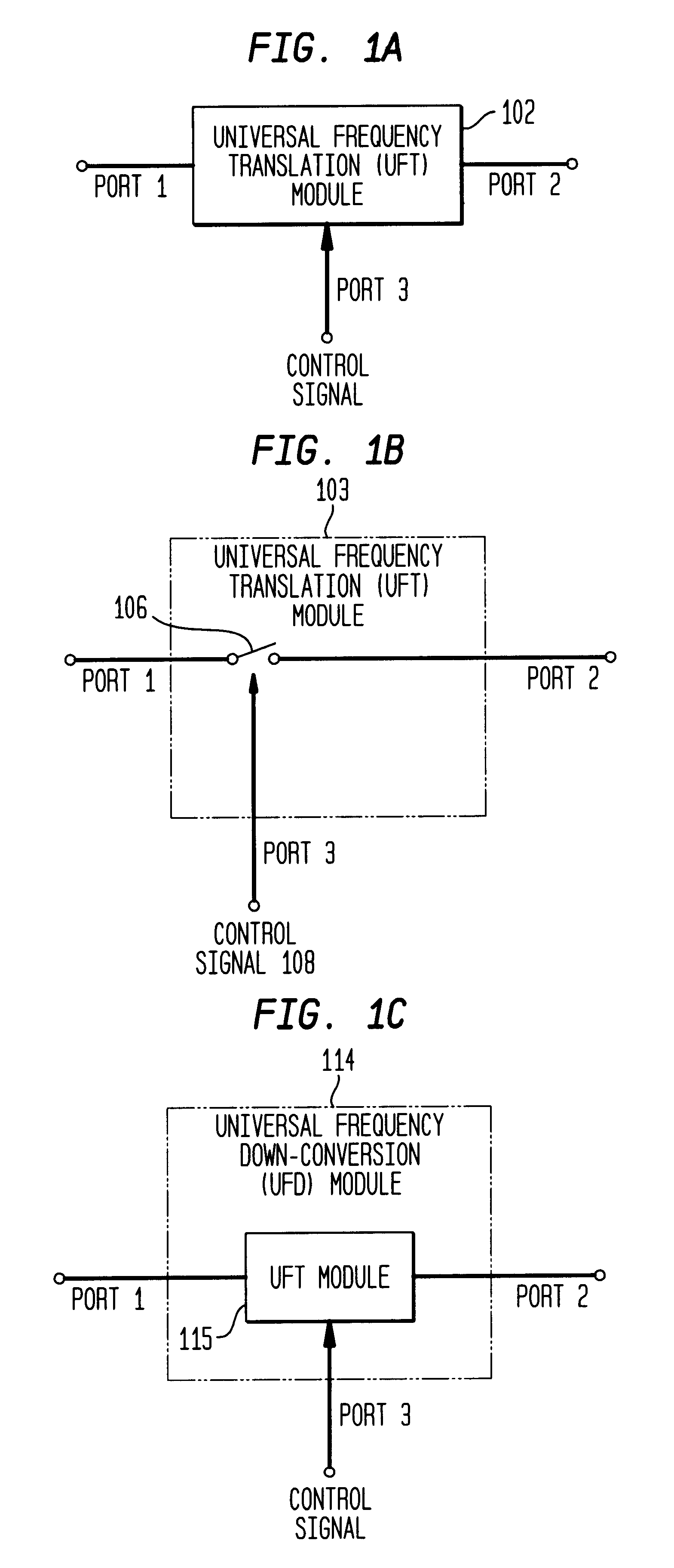
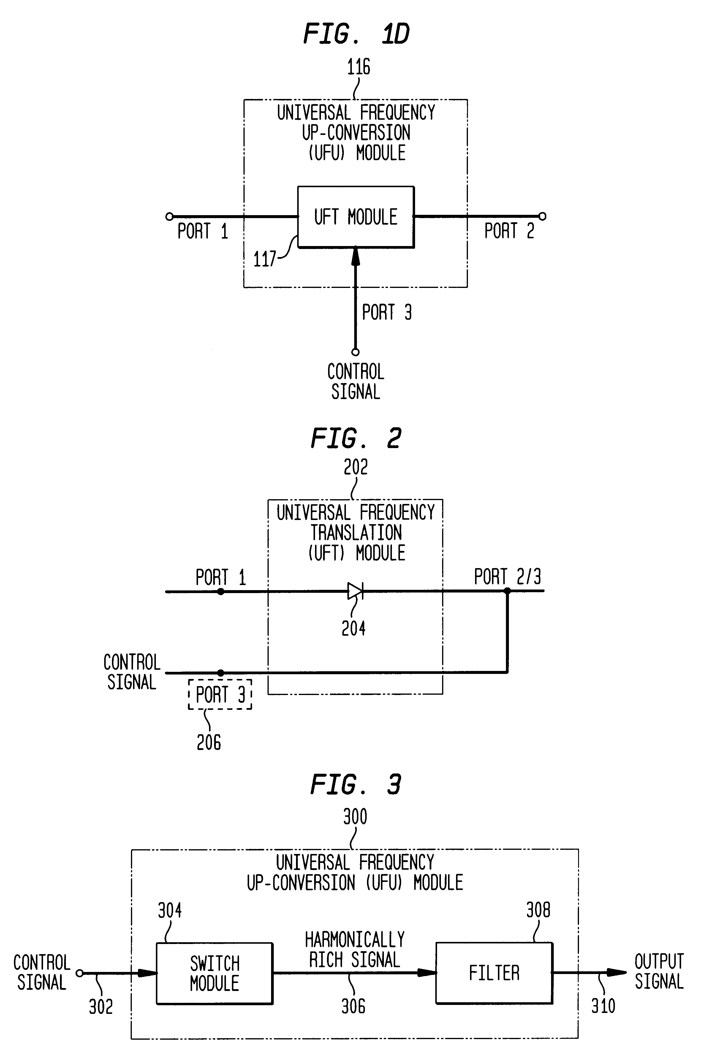
[0383]As noted above, the UFT module of the present invention is a very powerful and flexible device. Its flexibility is illustrated, in part, by the wide range of applications in which it can be used. Its power is illustrated, in part, by the usefulness and performance of such applications.

[0384]Example applications of the UFT module were described above. In particular, frequency down-conversion, frequency up-conversion, enhanced signal reception, and unified down-conversion and filtering applications of the UFT module were summarized above, and are further described below. These applications of the UFT module are discussed herein for illustrative purposes. The invention is not limited to these example applications. Additional applications of the UFT module will be apparent to persons skilled in the relevant art(s), based on the teachings contained herein.

[0385]For example, the present invention can be used in applications that inv...


PUM


Abstract

Methods, systems, and apparatuses for down-converting an electromagnetic (EM) signal by aliasing the EM signal, and applications thereof are described herein. Reducing or eliminating DC offset voltages and re-radiation generated when down-converting an electromagnetic (EM) signal is also described herein. Down-converting a signal and improving receiver dynamic range is also described herein.

Description

[0001]This application is a divisional of U.S. application Ser. No. 09 / 526,041, filed Mar. 14, 2000, which is incorporated by reference herein in its entirety.CROSS-REFERENCE TO OTHER APPLICATIONS[0002]The following applications of common assignee are related to the present application, and are herein incorporated by reference in their entireties:[0003]“Method and System for Down-Converting Electromagnetic Signals,” Ser. No. 09 / 176,022, filed Oct. 21, 1998.[0004]“Method and System for Frequency Up-Conversion,” Ser. No. 09 / 176,154, filed Oct. 21, 1998.[0005]“Method and System for Ensuring Reception of a Communications Signal,” Ser. No. 09 / 176,415, filed Oct. 21, 1998.[0006]“Integrated Frequency Translation And Selectivity,” Ser. No. 09 / 175,966, filed Oct. 21, 1998.[0007]“Applications of Universal Frequency Translation,” Ser. No. 09 / 261,129, filed Mar. 3, 1999.[0008]“Method and System for Down-Converting Electromagnetic Signals Having Optimized Switch Structures,” Ser. No. 09 / 293,095,...

Claims


Application Information

Patent Timeline
Patent Type & Authority Patents(United States)
IPC IPC(8): H03C3/00H03D3/00H03D7/00H03C3/40
CPCH03C3/40H03D3/006H03D7/00
Inventor SORRELLS, DAVID FBULTMAN, MICHAEL JCOOK, ROBERT WLOOKE, RICHARD CMOSES, JR., CHARLEY DRAWLINS, GREGORY SRAWLINS, MICHAEL W
Owner PARKER VISION INC
Why Eureka
Try Eureka