Peltier-cooled LED lighting assembly

a technology of led lighting and cooling plate, which is applied in the direction of fixed installation, lighting and heating apparatus, lighting applications, etc., can solve the problems of reducing unit operation efficiency, affecting unit life span, and insufficient thermal transfer from led(s) to the housing to maintain a desirable led temperature, so as to prevent condensation

Inactive Publication Date: 2005-11-15
ALTMAN STAGE LIGHTING
View PDF23 Cites 247 Cited by
  • Summary
  • Abstract
  • Description
  • Claims
  • Application Information

AI Technical Summary

Benefits of technology

[0038]According to another embodiment of the present invention there is provided a high-powered lighting assembly, further comprising: at least a cover bounding a display side of the circuit board, the cover in sealing contact with the display side of the circuit board, the cover in sealing contact with an inner surface of a rim on the insulation layer, and an outer surface of the rim in sealing contact with the housing, whereby the insulation layer prevents conductive thermal transfer from the housing to the cover and the cover prevents condensation on the array during the operation.
[0039]According to another embodiment of the present invention there is provided a high-powered lighting assembly, comprising: a heat sink plate in thermal contact with a housing, a light-emitting array, means for sensing a temperature of the array, means for cooling and transferring thermal energy from at least a first portion of the array to the heat sink plate, means for controlling the cooling means and maint...

Problems solved by technology

Specifically, as higher power LED(s) are used, and as higher concentrations of LED(s) are used, the heat generated detrimentally affects unit life span, and reduces unit operational efficiency.
In high use and in demanding situations, the thermal transfer from the LED(s), through the thermally connected heat spreading plate to the housing is insufficient to maintain a desirable LED temperature.
Unfortunately, thermal back-flow may occur as a housing is heated by the ambient atmosphere beyond an optimal point which allows thermal conduction back to the heat spreading plate.
In such situations, rapid LED degradation occurs and unit efficiency drops.
The above techniques for thermal removal have the common disadvantage of using direct passive conduction and convection heat transfer from the LED(s) to the heat sink or heat spreading plate and thereafter to the housing.
The passive nat...

Method used


Image

  • Peltier-cooled LED lighting assembly
  • Peltier-cooled LED lighting assembly
  • Peltier-cooled LED lighting assembly

Examples


Embodiment Construction

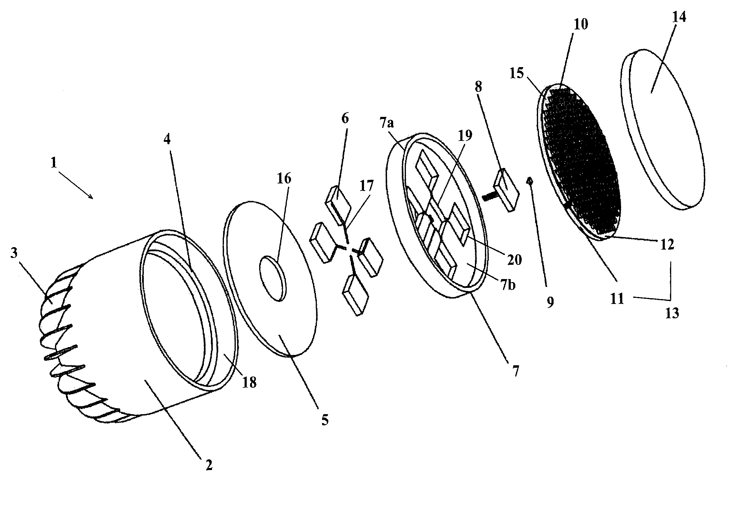
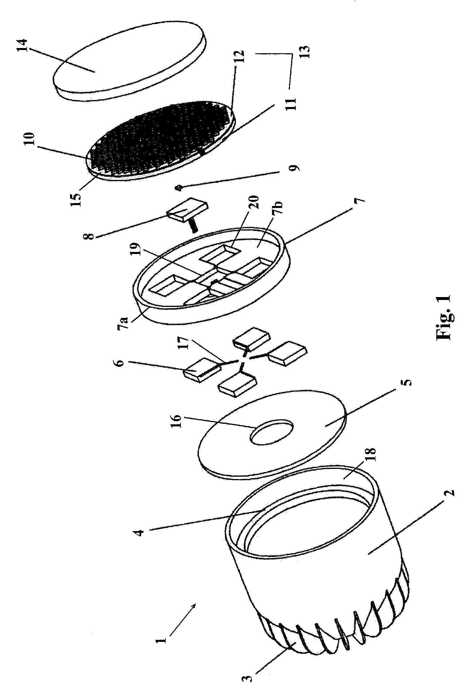
[0048]Referring now to FIG. 1, a lighting assembly 1 includes a cylindrically shaped housing 2 having a closed bottom end and an open top end. A plurality of fins 3 extend radially from the bottom end of housing 2 and aid in convective thermal transfer, as will be explained. A ring shaped mounting surface 4 extends continuously around an inner surface 18 at the top end of housing 2.

[0049]Housing 2 may be formed from any material suitable for a desired application including plastics and metals such as aluminum and steel. Housing 2 may additionally include brackets, threaded holes, or connection surfaces useful in mounting lighting assembly 1 to an external structure (not shown). Alternative embodiments to the present invention envision additional structures on housing 2 for speedy removal of thermal energy, including vents, liquid cooling structures, forced air structures, and fans (all not shown).

[0050]During assembly, a heat sink plate 5 seals tightly to mounting surface 4 and prov...


PUM


Abstract

A high-powered lighting assembly includes an easily sealed continuous thermal barrier and a solid-state actively controlled closed-loop refrigeration system to maximize operational efficiencies and increase unit life. The thermal barrier prevents thermal back-flow from a heat sink plate or a housing to a lighting array while insulating a control module and a thermal sensor with improved sealing geometry. The refrigeration system is optimally positioned to controllably pump heat from the lighting array to the heat sink plate.

Description

BACKGROUND OF THE INVENTION[0001]1. Field of the Invention[0002]The present invention relates to a high-powered lighting assembly utilizing a solid-state thermoelectric cooling system for primary use in theatrical or architectural lighting fixtures. More specifically, the present invention relates to a lighting assembly having a continuous sealable thermal barrier and an active closed-loop refrigeration system employing a Peltier-effect thermo-electric module(s) (hereinafter TEM(s)).[0003]2. Description of the Related Art[0004]With the emergence of increasingly higher-powered Light Emitting Diodes (LED(s)) in lighting arrays, and their use in theatrical and architectural illumination applications, there has been a corresponding increase in heat generation concerns.[0005]Specifically, as higher power LED(s) are used, and as higher concentrations of LED(s) are used, the heat generated detrimentally affects unit life span, and reduces unit operational efficiency.[0006]As both high powe...

Claims


Application Information

Patent Timeline
IPC IPC(8): F21V29/00F21S8/00
CPCF21V29/004F21V29/773F21V29/54F21V29/713F21W2131/10F21W2131/107F21W2131/406Y10S362/80F21Y2101/02F21Y2115/10F21V29/74
Inventor RYAN, JOHN T.
Owner ALTMAN STAGE LIGHTING
Why Eureka
Try Eureka