Gear motor for power tool

a gear motor and power tool technology, applied in the direction of portable power tools, toothed gearings, drilling machines and methods, etc., can solve the problems of stability of the motor and little room for reducing the overall length of the drill bi

Inactive Publication Date: 2005-11-22
JOHNSON ELECTRIC SA
View PDF18 Cites 23 Cited by
  • Summary
  • Abstract
  • Description
  • Claims
  • Application Information

AI Technical Summary

Benefits of technology

[0005]To ensure radial movement of the shaft is kept to a minimum, the present invention, while combining the gearbox cover and

Problems solved by technology

While this approach works well in aligning the motor to the gearbox, there is little room for reducing the overall length of the drill as desired by current market trends.
Howeve

Method used


Image

  • Gear motor for power tool
  • Gear motor for power tool
  • Gear motor for power tool

Examples


Embodiment Construction

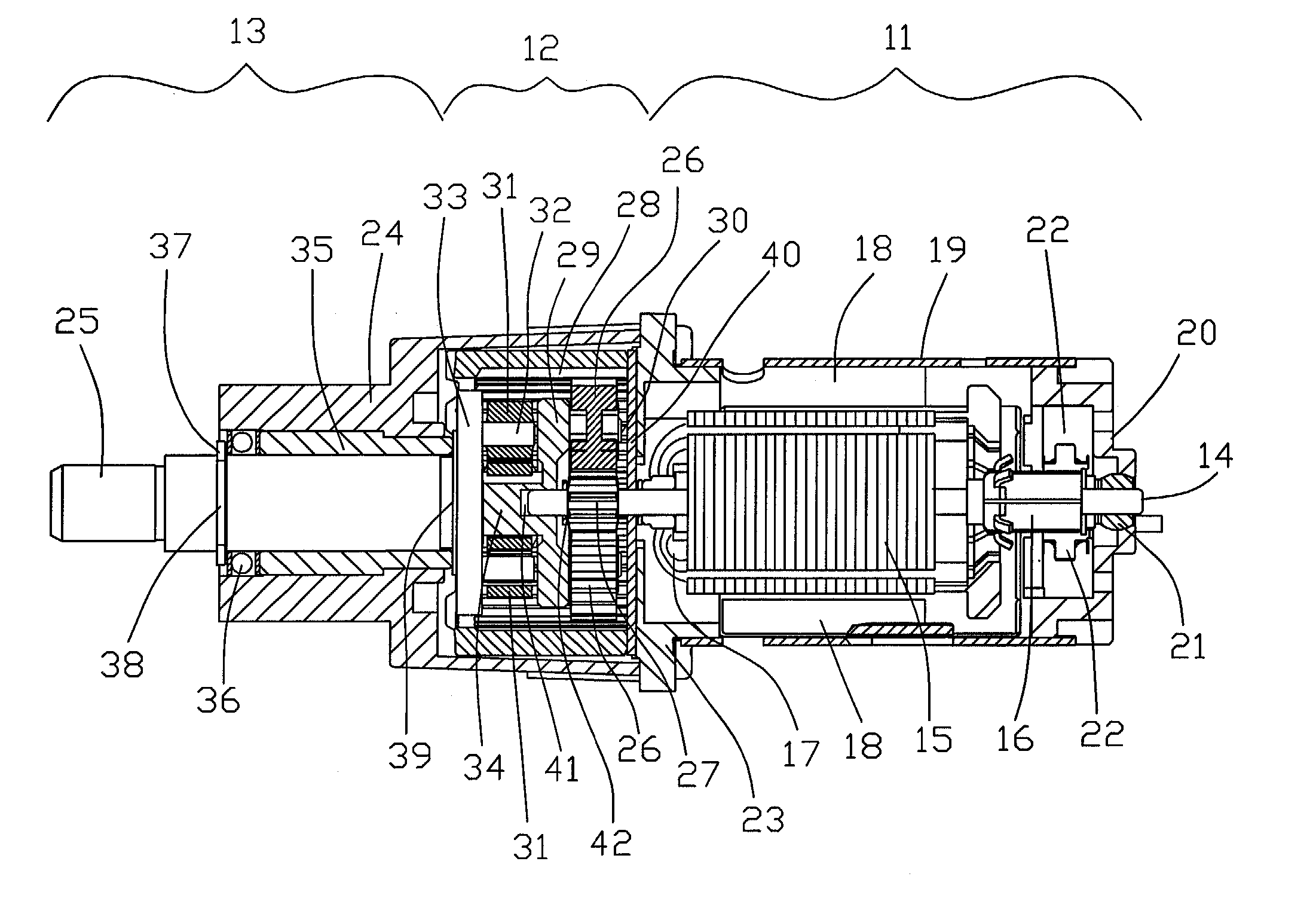
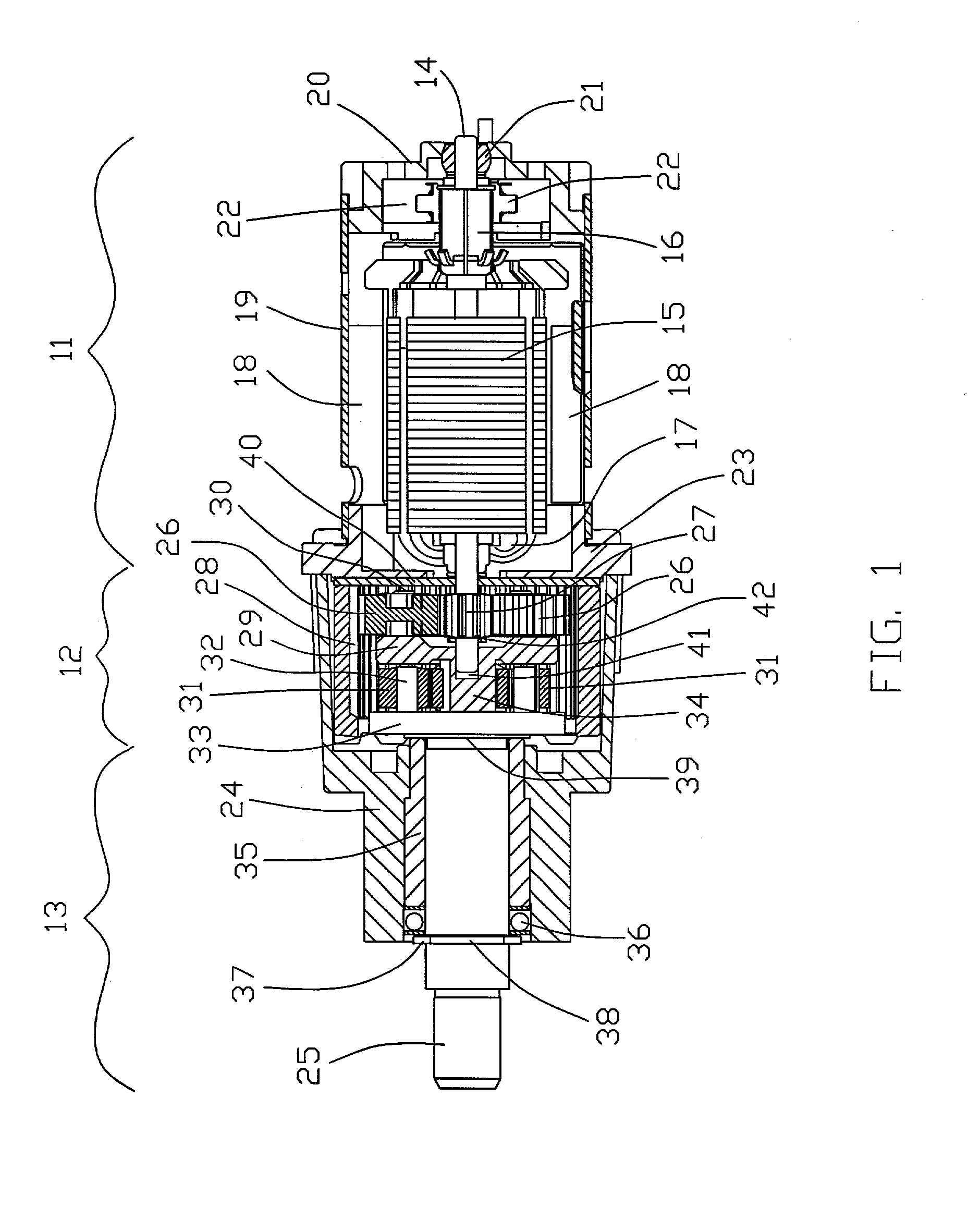
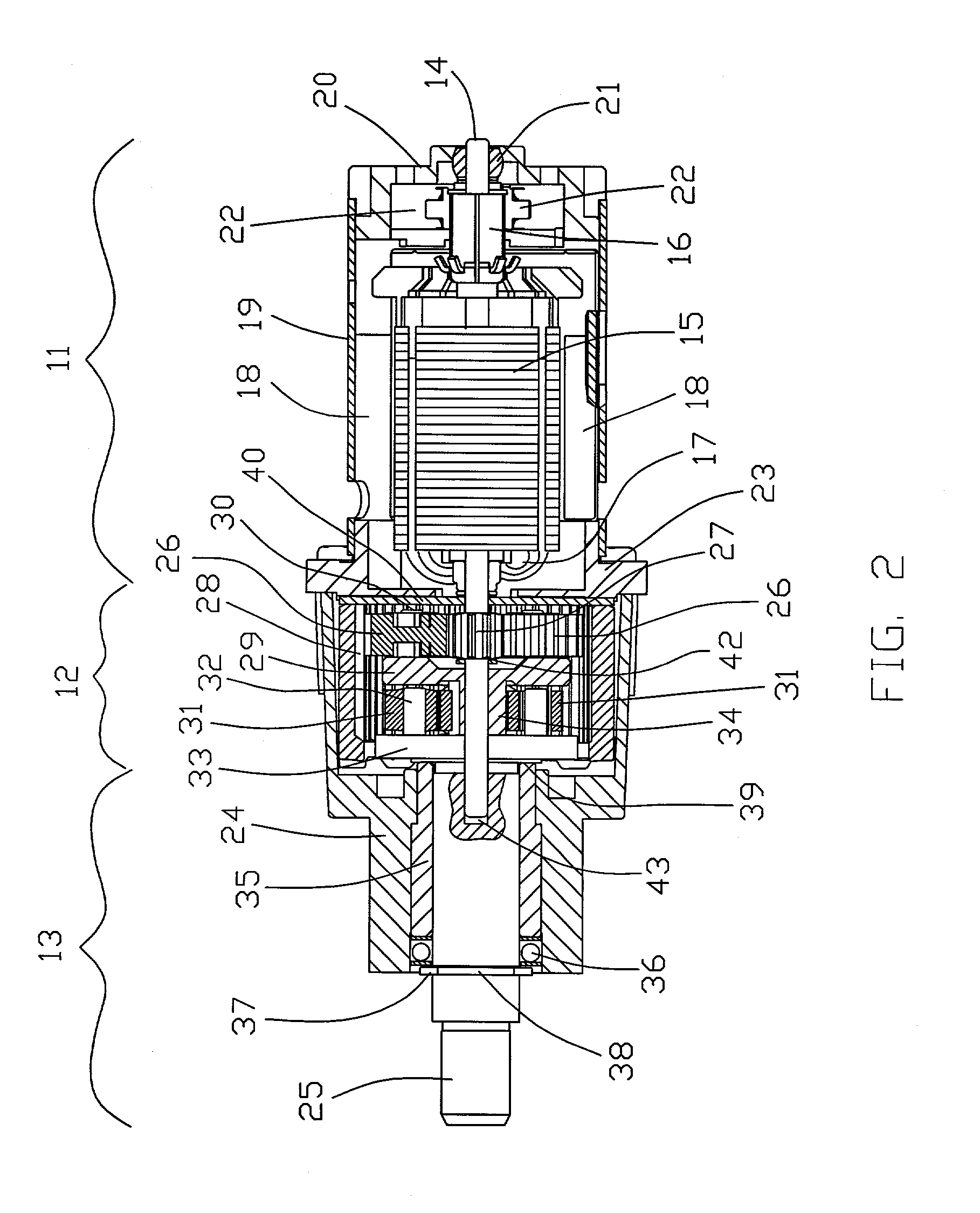
[0014]FIG. 1 shows a motor / gearbox combination suitable for use in a hand held power tool such as a drill or electric screwdriver. The combination has a compact overall length. The combination can be divided into two sections, namely: a motor section 11 and a gearbox section 12 which includes an output section 13.

[0015]The motor section 11, shown on the right, incorporates a DC motor having a permanent magnet stator and a wound rotor. The rotor has a shaft 14, a rotor core 15 and commutator 16 fitted to the shaft 14, with rotor windings 17 wound around the rotor core 15 and terminated on the commutator 16.

[0016]The stator has permanent magnets 18 disposed inside a tubular housing 19. An end cap 20 closes off the right hand end of the tube 19. The end cap 20 is made of an insulating synthetic resin and supports a bearing 21, brush gear 22 and motor terminals (not shown). The bearing 21 is a self-aligning oil-impregnated sintered bronze bushing in which one end of the rotor shaft is j...


PUM


Abstract

A compact gearbox/motor combination for a portable power tool has a single partition plate 23 closing an end of the gearbox housing 24 and the motor housing 19. A shaft 14 of the motor is journalled at one end in a self-aligning bearing 21 supported by an end cap 20 of the motor. The other end of the motor shaft 14 is journalled in a hole 41 in a gear carrier 29 of the gearbox.

Description

BACKGROUND[0001]This invention relates to portable power tools and in particular, to a motor and gearbox for a portable power tool. It has special relevance to portable hand held drills and it is in this context that the invention will be explained.[0002]Portable hand held tools such as drills are driven by electric motors, either battery or mains powered. To increase the output torque of the drill, the motor drives the chuck through a speed reduction gear train. To keep the drill compact and for maximum drilling force, epicyclic gearboxes are preferred.[0003]Presently, the drill manufacturer receives a motor and a separate gearbox complete with an output shaft. The motor and gearbox are connected together using a special adapter plate and then the combined motor and gearbox are assembled into the casing of the drill. While this approach works well in aligning the motor to the gearbox, there is little room for reducing the overall length of the drill as desired by current market tre...

Claims


Application Information

Patent Timeline
IPC IPC(8): B25F5/00B23B45/02F16H1/28
CPCB25F5/001F16H1/46
Inventor TANG, ERNEST
Owner JOHNSON ELECTRIC SA
Why Eureka
Try Eureka