Golf club head and method of manufacturing the same

a technology of golf club head and manufacturing method, which is applied in the field of golf club head, can solve the problems of insufficient strength of the central portion of the face for directly hitting the ball, difficult to form a stable striking surface, and inability to plan the respective dimensions and strengths, etc., to achieve the effect of increasing the flying distance of the ball, enhancing repellency, and sufficient strength

Inactive Publication Date: 2005-11-22
DAIWA SEIKO CORPORATION
View PDF10 Cites 47 Cited by
  • Summary
  • Abstract
  • Description
  • Claims
  • Application Information

AI Technical Summary

Benefits of technology

[0013]The invention has been devised to overcome the above-described problems, and its object is to provide a golf club head which makes it possible to make the face member thin by the use of a material having small variations in the strength, and which makes it possible to ensure sufficient strength with respect to the shock at the time of impacting, enhance the repellency at the time of impacting, increase the flying distance of the ball, and make clear the striking feel at the time of impacting.

Problems solved by technology

However, since the face members of the conventional type in which the thickness is varied for the respective portions are fabricated by forging, variations of the thickness of the face members and their waviness are large, so that it is difficult to fabricate the respective portions with planned dimensions and strengths.
However, since the metallic face member subjected to rolling is a metal plate member having a uniform thickness in its entirety, and the variations of the strength of the respective portions are small, if the face member is made thin, the central portion of the face is easily flexed at the instant of impacting, and sufficient rebounding can be obtained by the overall face, but the strength of the central portion of the face for directly hitting the ball cannot be sufficiently obtained.
At the same time, it is difficult to form a stable striking surface.
For example, it is impossible to obtain a planned configuration, and variations in the strength are large.
Accordingly, there has been a tendency that breakage is likely to start from the thin-walled portion where the variations in the strength are large.
In this case, if the metal face whose thickness is varied is fabricated by casting, the metallographic structure becomes coarse, and voids are likely to be produced, so that variations are likely to occur in the strength.
In addition, if such a metal face is fabricated by forging from a metal mass, since large plastic deformation takes place, the metallographic structure becomes dense, but its density is not stable, and variations occur in the density of the structure.
Moreover, since the metal face is normally manufactured by hot forging, the characteristics of the material undergo a change, so that the durable strength declines.
Thus the conventional metallic face which has been fabricated by casting or forging and whose thickness is varied has a problem in that there are variations in the strength, and breakage or the like is likely to occur.

Method used


Image

  • Golf club head and method of manufacturing the same
  • Golf club head and method of manufacturing the same
  • Golf club head and method of manufacturing the same

Examples


first embodiment

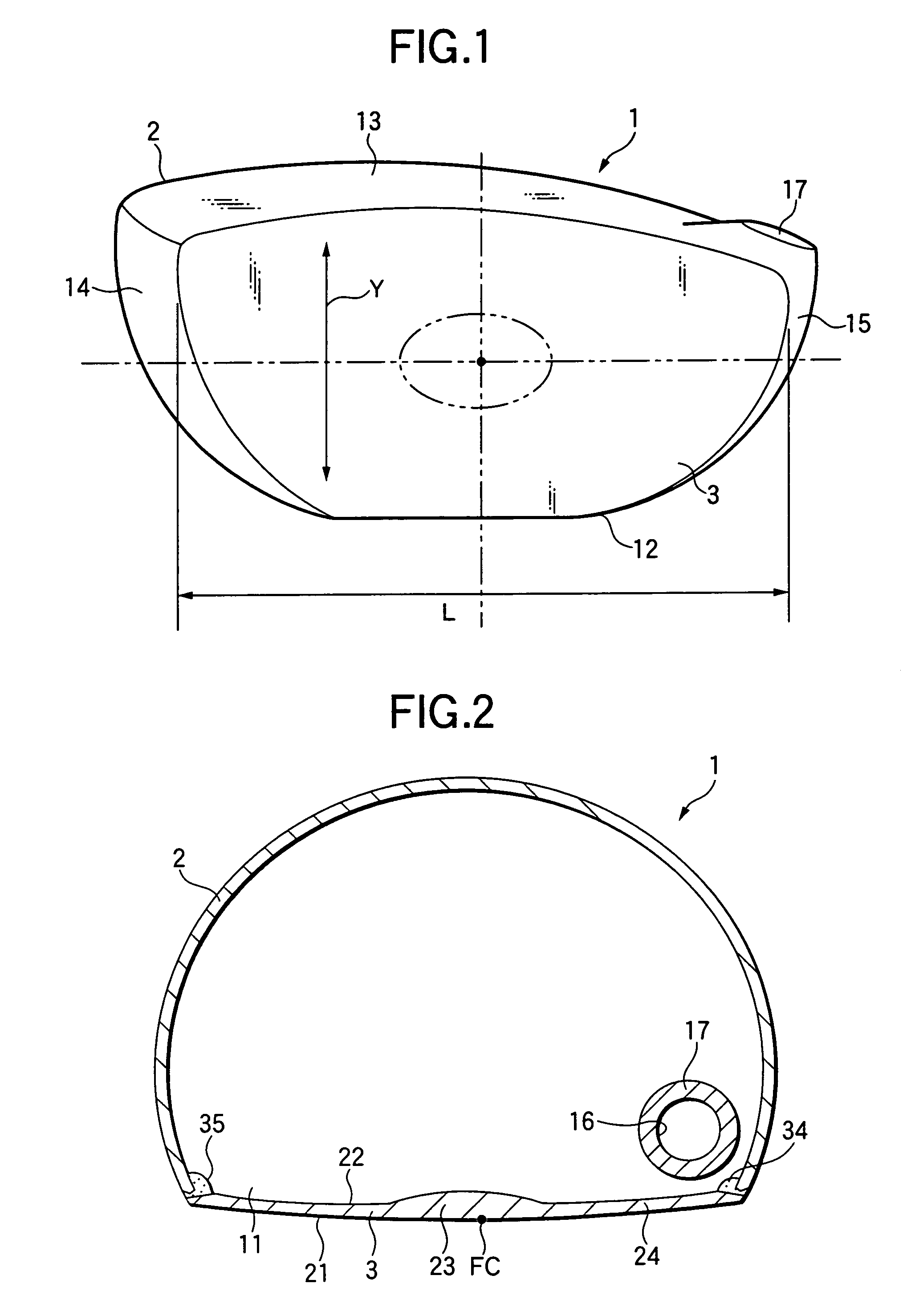
[0067]FIGS. 1 to 4 show a golf club head of a wood type which is a metallic hollow head in accordance with a first embodiment of the invention.

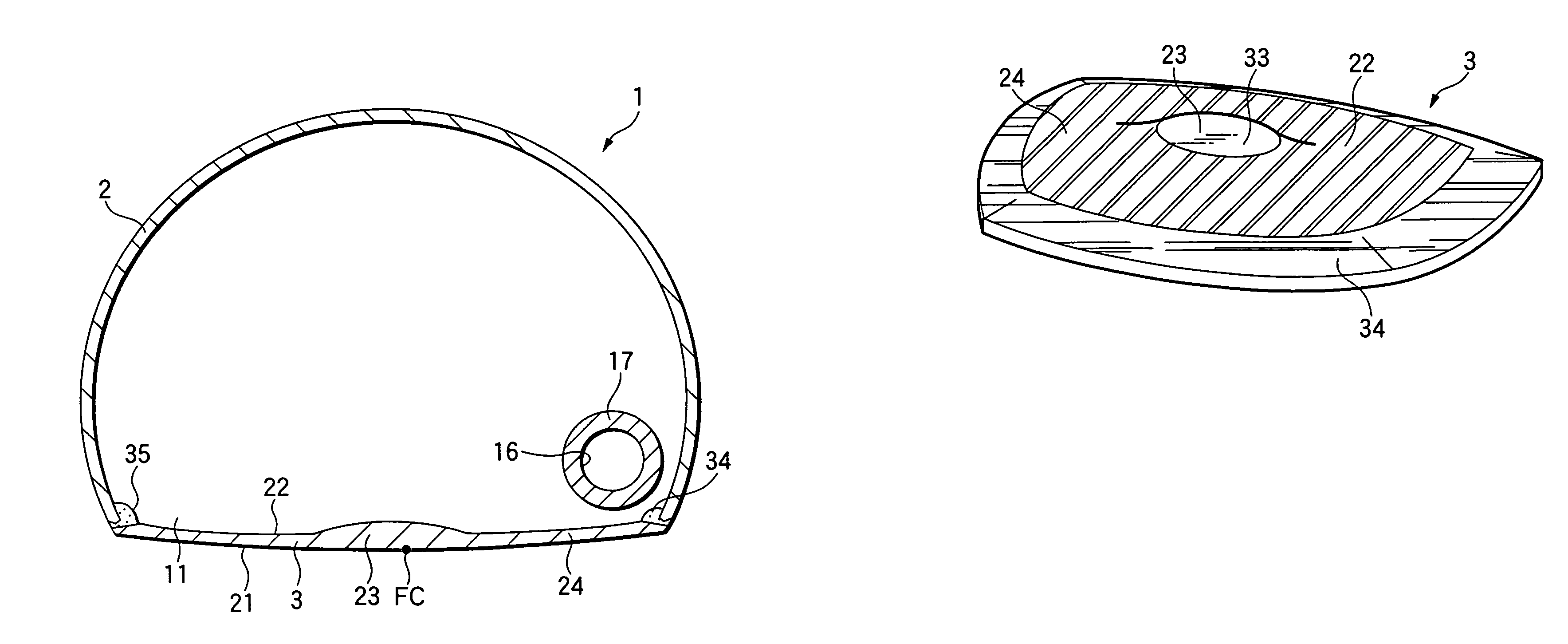
[0068]This golf club head 1 has a head body 2 formed by a hollow member, and a face member 3 for forming a face. As shown in FIG. 2, an opening 11 is formed in the head body 2 on the face side. With the golf club head 1, a lower surface portion of the head body 2 is formed as a sole 12, an upper surface portion thereof is formed as a top 13, and left- and right-hand portions of the face member 3 are respectively formed as a toe 14 and a heel 15. A shaft securing portion 17 having a shaft securing hole 16 for attaching an unillustrated club shaft is formed on the heel 15 side.

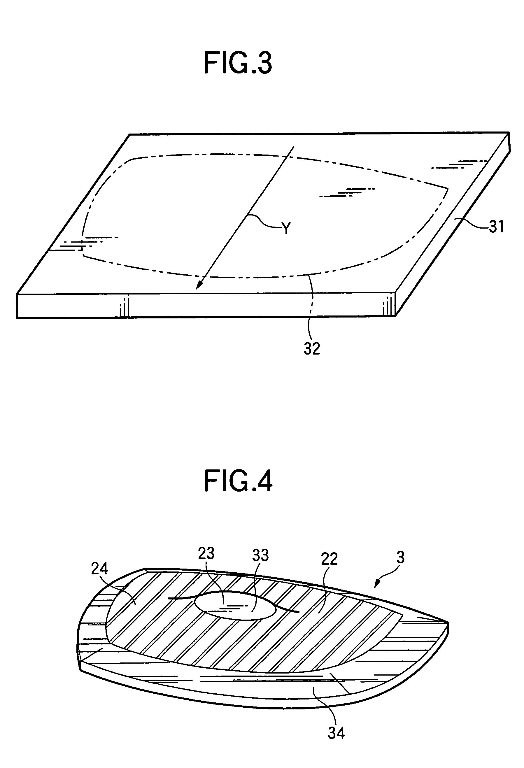
[0069]The face member 3 is disposed at the opening 11 of the aforementioned head body 2. The shape of the face member 3 is that of a contour conforming to the shape of the opening 11 of the head body 2, as shown in FIG. 2. The face member 3 is fixed to the head body 2 by ...

second embodiment

[0080]FIG. 5 shows a golf club head in accordance with a second embodiment of the invention. In the golf club head 1 in accordance with this embodiment, when the reverse surface 22 of the face member 3 is shaved down by shaving, the portion of the thick-walled portion 23 in the central area is processed into the shape of a top portion which is not flat but rounded. According to this embodiment, since the thick-walled portion 23 and the thin-walled portion 24 continue smoothly at their boundary, the stress does not concentrate in the boundary, and the overall strength of the face member 3 increases.

third embodiment

[0081]FIG. 6 shows a golf club head in accordance with a third embodiment of the invention. In the golf club head 1 in accordance with this embodiment, when the reverse surface 22 of the face member 3 is shaved down by shaving, machining is effected over the area covering the thick-walled portion 23 in the vicinity of the face center FC and the thin-walled portion 24 surrounding it, such that the flat top portion is not left, and the overall reverse surface 22 is cut into a rounded gentle shape. In this embodiment as well, since the thick-walled portion 23 and the thin-walled portion 24 continue smoothly at their boundary, the stress does not concentrate in the boundary, and the overall strength of the face member 3 increases.

[0082]Further, although not shown, the overall reverse surface 22 may be processed into a conical shape in which it is pointed in the vicinity of the center of the thick-walled portion 23.

[0083]It should be noted that, as the processing method for forming the t...


PUM

PropertyMeasurementUnit
thicknessaaaaaaaaaa
thicknessaaaaaaaaaa
thicknessaaaaaaaaaa

Abstract

A golf club head of the invention includes a head body formed by a hollow member, and a face member for forming a face. The face in which a thick-walled portion and a thin-walled portion are formed by forging a metal plate subjected to rolling.

Description

BACKGROUND OF THE INVENTION[0001]The present invention relates to a golf club head in which a fringe portion of a face member is fixed to a head body by welding.[0002]As compared with conventional golf club heads, with recent golf club heads, the volume of the head has become large for the ease of striking the ball and to improve stability and increase the flying distance. Since such a golf club head is so configured as to increase the volume of the head while avoiding the tendency of the club head becoming heavy, the respective portions of the head in terms of thickness are formed to be thin, and metallic materials having fixed thicknesses are in many cases used for the respective portions of the head. For example, in the case of a face, a face member is used which is processed into a plate member with a uniform thickness made of a metal such as a titanium alloy. According to the face member constituted by such a plate member with a uniform thickness, it is possible to thin the ove...

Claims


Application Information

Patent Timeline
Patent Type & Authority Patents(United States)
IPC IPC(8): A63B53/04B21K17/00B23P15/00
CPCA63B53/04B23P15/00A63B53/0466B21K17/00A63B2053/0416A63B2053/0458A63B2053/0462A63B2209/00A63B53/0462A63B53/0458A63B53/0416A63B60/00
Inventor KUSUMOTO, HARUNOBU
Owner DAIWA SEIKO CORPORATION
Why Eureka
Try Eureka