
Rotor assembly and stator assembly for an electrical machine

Inactive Publication Date: 2005-11-22
MINEBEA CO LTD
View PDF17 Cites 62 Cited by
  • Summary
  • Abstract
  • Description
  • Claims
  • Application Information

AI Technical Summary

Benefits of technology

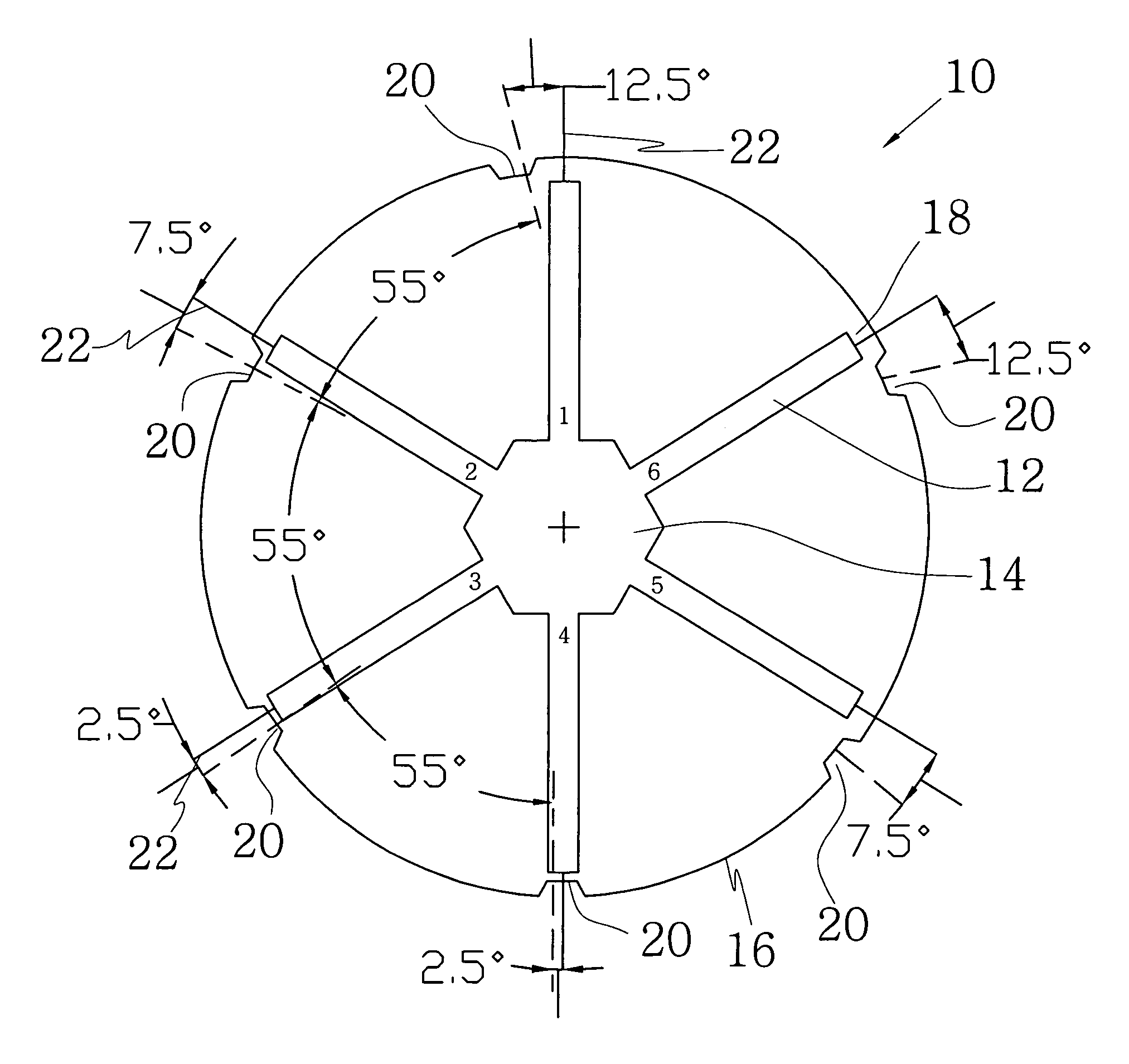
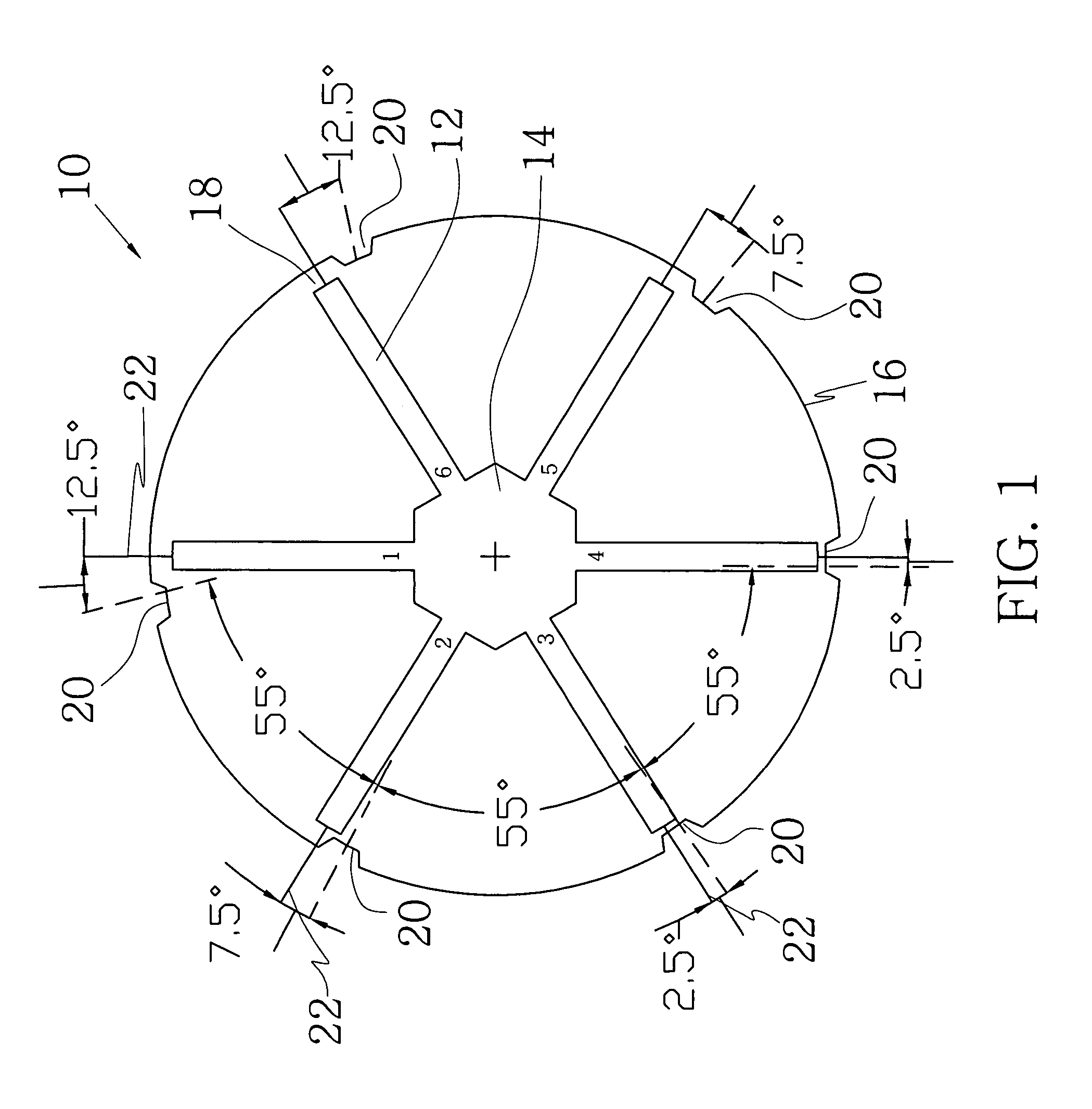
[0018]According to the present invention a rotor assembly for an electrical machine is provided, comprising a rotor body of generally cylindrical shape having an substantially cylindrical surface configured for facing an air-gap between the rotor assembly and a stator of the electrical machine, and permanent magnets embedded in said rotor body. In the air-gap facing surface of the rotor body grooves are formed for manipulating the distribution of magnetic flux created by said permanent magnets. By providing grooves in the air-gap facing surface of the rotor body, it is possible to control the flux concentration of the magnetic flux created by the permanent magnets, passing from the rotor assembly through the air-gap to the stator. By controlling the flux concentration or flux distribution the cogging torque can be reduced. The operation of the electrical machine thus can be tuned by choosing an appropriate shape of the grooves in the air-gap facing surface of the rotor body.
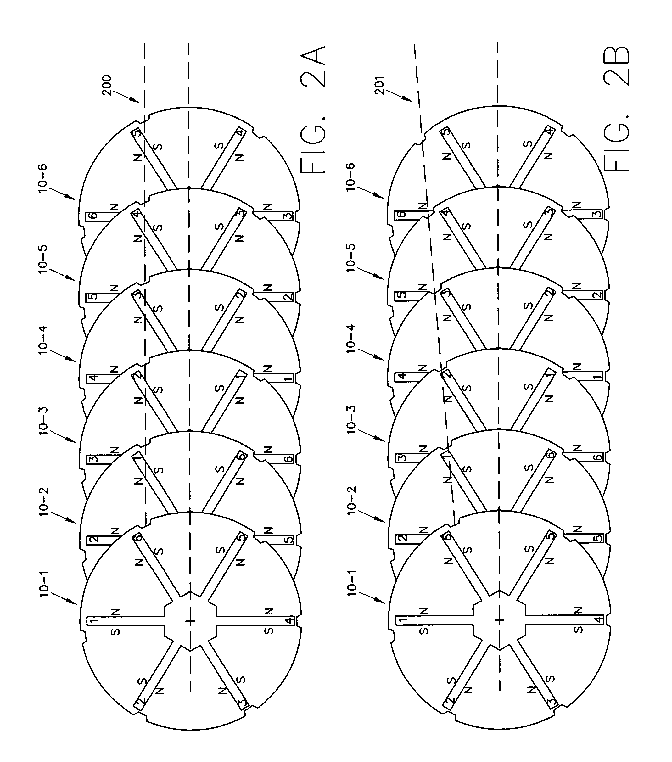
[0019]In one embodiment of a rotor assembly having embedded magnets, the magnets extend substantially radially through the rotor body. According to the present invention, the grooves preferably are provided in the neighbourhood of the end faces of at least some of the permanent magnets. For effectively reducing the cogging torque, it is preferred that skewed grooves are formed in said air-gap facing surface of the rotor body which extend along the length of said surface with a predefined angle to the axial line in the axial direction of the rotor body. By providing such skewed grooves, the present invention can reduce the cogging torque down to acceptable values without any additional technological or material expenses. The grooves in the air-gap facing surface of the rotor body, when appropriately designed and placed, are sufficient to manipulate the distribution of the magnetic flux to optimise the motor operation.
[0022]Based on that same inventive concept, the present invention also provides a stator assembly for an electrical machine, comprising a stator body of generally cylindrical shape having a stator yoke and stator poles, said stator poles having end faces facing an air-gap between the stator assembly and a rotor of the electrical machine. In the end faces of the stator poles, grooves are formed for manipulating the distribution of magnetic flux created between said stator body and said rotor of the electrical machine. The grooves in the end faces of the stator poles have a similar effect as the grooves in the air-gap facing surface of the rotor body for manipulating the air flux distribution and thus, by appropriately arranging the grooves, reducing or eliminating the cogging torque effect.
[0025]While the prior art arrangement of embedded magnets provided for only two degrees of freedom for controlling motor parameters, such as the radial distribution of the electromagnetic induction of the air-gap and flux concentration, namely the widths of each magnet and the height of each magnet, the present invention allows further parameters for motor tuning. According to the present invention, the motor can be tuned as a function of the width, length and inclination angle of the skewed grooves in the air-gap facing surface of the rotor body or the stator poles. Therefore, it is easier to influence the flux concentration and distribution of the electromagnetic induction in the air gap as with the arrangements according to the prior art. By optimising the size, shape and position of the grooves it is possible to reduce the cogging torque without the necessity of any skewing technique which has been used in the prior art. The design of the grooves will depend on the design of the motor. Presently preferred values of the inclination or shifting angle to the axial line are between 10 and 60 degrees, preferably between 20 and 40 degrees.
[0027]According to the present invention, there is no retaining tube necessary for protecting the permanent magnets and holding the permanent magnets in place. Accordingly, the size of the air-gap can be reduced and the energy from the magnet can be transferred more efficiently to the stator so that there is less energy loss. As a consequence, the volume of magnetic material can be reduced when compared with a surface magnet designed under equal conditions otherwise.

Problems solved by technology

Accordingly, magnet energy dissipated in this area can't be used efficiently.
With the radial arrangement of the permanent magnets and the stator poles, as shown and described in the prior art, a problem may arise in that the regular arrangement of the permanent magnets and stator poles produces a cogging torque effect which is disadvantageous in the operation of the permanent magnet motor.
Skewed magnetization of the rotor poles, however, creates an axial component of the magnetic force and thus a loss of torque.
Further, the problem of the cogging torque produced during operation of the permanent magnet motor has not yet been solved satisfactorily for rotors having embedded magnets of the type described above.
In fact, one of the biggest technological disadvantages of a motor design comprising embedded or buried magnets is that it appears to be virtually impossible to skew the rotor assembly, physically or magnetically, so that an existing cogging torque can be reduced only by design optimization, or skewing the stator.
Skewing of the stator usually means that the stator poles have to be deformed so that it will be more difficult to apply the stator windings onto the skewed stator.
This leads to cancelling of harmonics in the cogging torque wave form.
The “Broadbent shift” requires cutting the magnets into pieces in the axial direction which leads to significant difficulties during the manufacture and assembly procedure of the rotor assembly.

Method used


Image

  • Rotor assembly and stator assembly for an electrical machine
  • Rotor assembly and stator assembly for an electrical machine
  • Rotor assembly and stator assembly for an electrical machine

Examples


Embodiment Construction

[0037]FIG. 1 schematically shows a sectional view through a lamination for forming a rotor assembly according to the present invention. The lamination 10 forms one axial section of the rotor body, having a generally cylindrical shape comprising slots 12 which radially extend from an inner opening 14 of the rotor body towards the outer periphery 16 thereof. A number of such laminations 10 are arranged on top of each other to form a rotor body having slots which extend radially and axially through the rotor body. Permanent magnets (not shown) will be embedded in the slots, wherein the laminations 10 form a magnetic core as well as a yoke of the rotor assembly. The configuration of the lamination 10 shown in FIG. 1 is adapted for an inner-rotor motor configuration wherein the inner opening 14 may be used for mounting the rotor body on a hub or a shaft. Of course, it is also within the scope of the present invention to provide an outer-rotor configuration in which the features of the ro...


PUM


Abstract

The present invention relates to a rotor assembly for an electrical machine, comprising: a rotor body of generally cylindrical shape having a substantially cylindrical surface configured for facing an air-gap between the rotor assembly and a stator of the electrical machine, and permanent magnets embedded in said rotor body, wherein grooves are formed in said air-gap facing surface for manipulating the distribution of magnetic flux created by said permanent magnets.

Description

[0001]This disclosure claims the filing date benefit of European Patent application No. 03 003 690.9 filed Feb. 18, 2003.FIELD OF THE INVENTION[0002]The present invention relates to a rotor assembly and a stator assembly of an electrical machine, in particular a permanent magnet (P.M) electrical machine comprising such a rotor assembly or stator assembly. In general, the invention relates to the field of electrical motors comprising permanent magnets which can be configured to include an inner rotor surrounded by a stator (Innenläufermotor) or an outer rotor configuration (Auβenläufermotor). Electrical machines having an interior rotor include a rotor assembly which is mounted on the rotor shaft and one or more permanent magnets as well as a stator assembly, such as a stator laminated from a number of metal sheets, comprising windings. The rotor assembly is coaxially inserted into the stator assembly. In electrical machines having outer rotors, the rotor assembly surrounds the stato...

Claims


Application Information

Patent Timeline
IPC IPC(8): H02K1/27H02K29/03H02K1/14H02K1/22H02K1/16H02K21/14
CPCH02K1/146H02K1/2766H02K29/03H02K2201/06
Inventor POPOV, VLADIMIR VLADIMIROVICH
Owner MINEBEA CO LTD
Learn More