
Piezoelectric electroacoustic transducer

a technology of electroacoustic transducers and electroacoustic waves, which is applied in piezoelectric/electrostrictive transducers, generators/motors, and cylindrical diaphragms. it can solve the problems of bending vibration generated by laminated bodies and achieve the effect of simple connection structur

Inactive Publication Date: 2005-11-29
MURATA MFG CO LTD
View PDF18 Cites 17 Cited by
  • Summary
  • Abstract
  • Description
  • Claims
  • Application Information

AI Technical Summary

Benefits of technology

[0009]To overcome the above-described problems, preferred embodiments of the present invention provide a piezoelectric electroacoustic transducer which eliminates the need for the interconnection between main surface electrodes and internal electrodes, and which enables construction of a bimorph diaphragm using a simple connection structure.
[0010]Further, preferred embodiments of the present invention provide a piezoelectric electroacoustic transducer in which the polarization process is easily performed.
[0013]In preferred embodiments of the present invention, since bending vibration is generated by interconnecting the top and bottom main surface electrodes and applying an alternating voltage across the main surface electrodes and internal electrodes, unlike conventional diaphragms, a complicated interconnection between the main surface electrodes and internal electrodes is not required. This results in simplification of the structure and reduction in the manufacturing cost.
[0016]In a three-layered laminated body, since there is no potential difference between the two internal electrodes, the intermediate layer does not contribute to a bending vibration, and only the top and bottom ceramic layers vibrate in a bending mode. The thinner the ceramic layer is, the larger the displacement thereof is. Accordingly, if the overall thickness of the laminated body is set to a constant value and the thickness of the intermediate layer is greater than the thicknesses of the top and bottom ceramic layers, the thicknesses of the top and bottom ceramic layers contributing to a bending vibration are relatively thin, which results in increased displacement. If the intermediate ceramic layer is too thick, however, the top and bottom ceramic layers will be too thin, which reduces the strength thereof, leading to a failure to yield a large displacement. Therefore, by setting the thickness of the intermediate layer to about 50 percent to about 80 percent of the overall thickness of the laminated body, a much larger sound pressure is achieved.
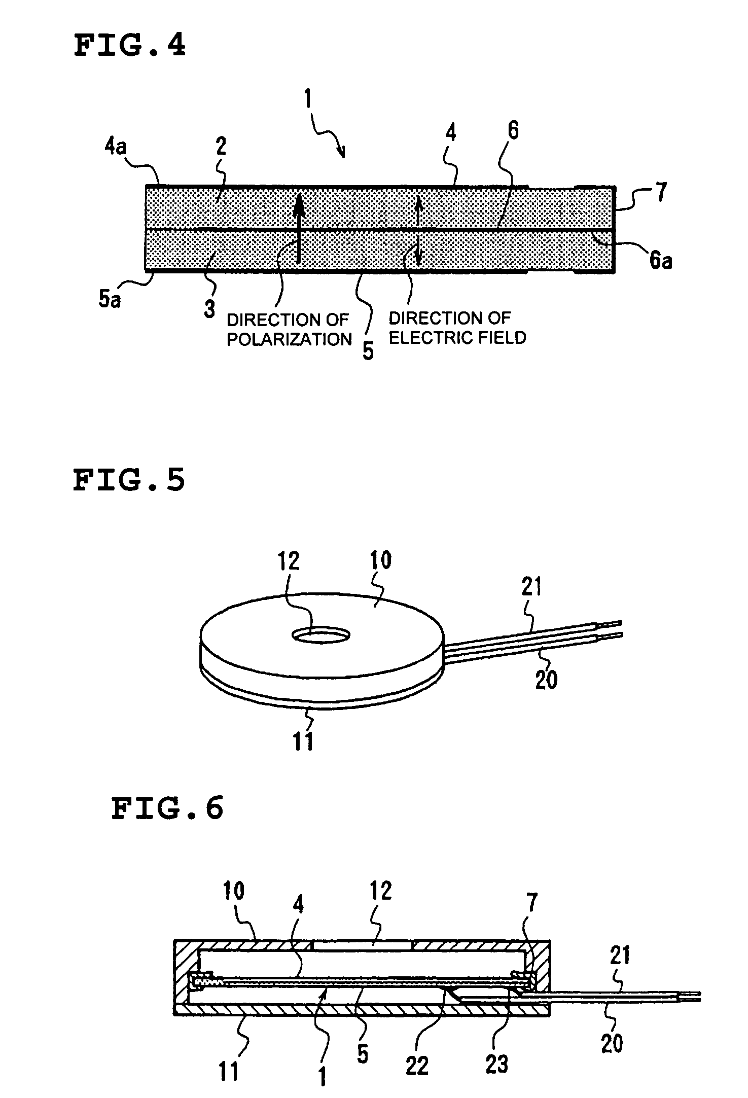
[0017]Moreover, in accordance with the first preferred embodiment of the present invention, preferably, the laminated body is constituted of a sintered body obtained by laminating two or three ceramic green sheets via an electrode film, and simultaneously firing the laminated green sheets, and then all of the ceramic layers are polarized in the same direction with respect to the thickness direction by applying a voltage across the main surface electrodes provided on the top and bottom surfaces of the laminated body. Alternatively, the laminated body may be obtained by laminating and adhering a plurality of ceramic plates which have been previously fired and polarized. This method, however, does not produce a thin laminated body, which results in decreased sound pressure. In contrast, laminating ceramic layer sheets via an electrode film, and simultaneously firing the laminated ceramic layer sheets produces a laminated body which is very thin, which results in an increased sound pressure. In addition, since the polarization direction of each ceramic sheet of the laminated body is the same, the polarization process does not require the application of a voltage across the internal electrodes and the main surface electrodes, unlike the conventional method. That is, polarization is achieved by applying a voltage across only the top and bottom main surface electrodes, which greatly simplifies the polarization process.

Problems solved by technology

Therefore, if an alternating voltage is applied as described above, for example, when the top ceramic layer expands, the bottom ceramic layer contracts, which causes the laminated body to generate a bending vibration.

Method used


Image

  • Piezoelectric electroacoustic transducer
  • Piezoelectric electroacoustic transducer
  • Piezoelectric electroacoustic transducer

Examples


Embodiment Construction

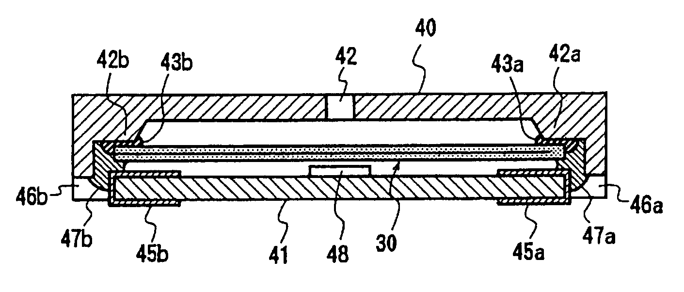
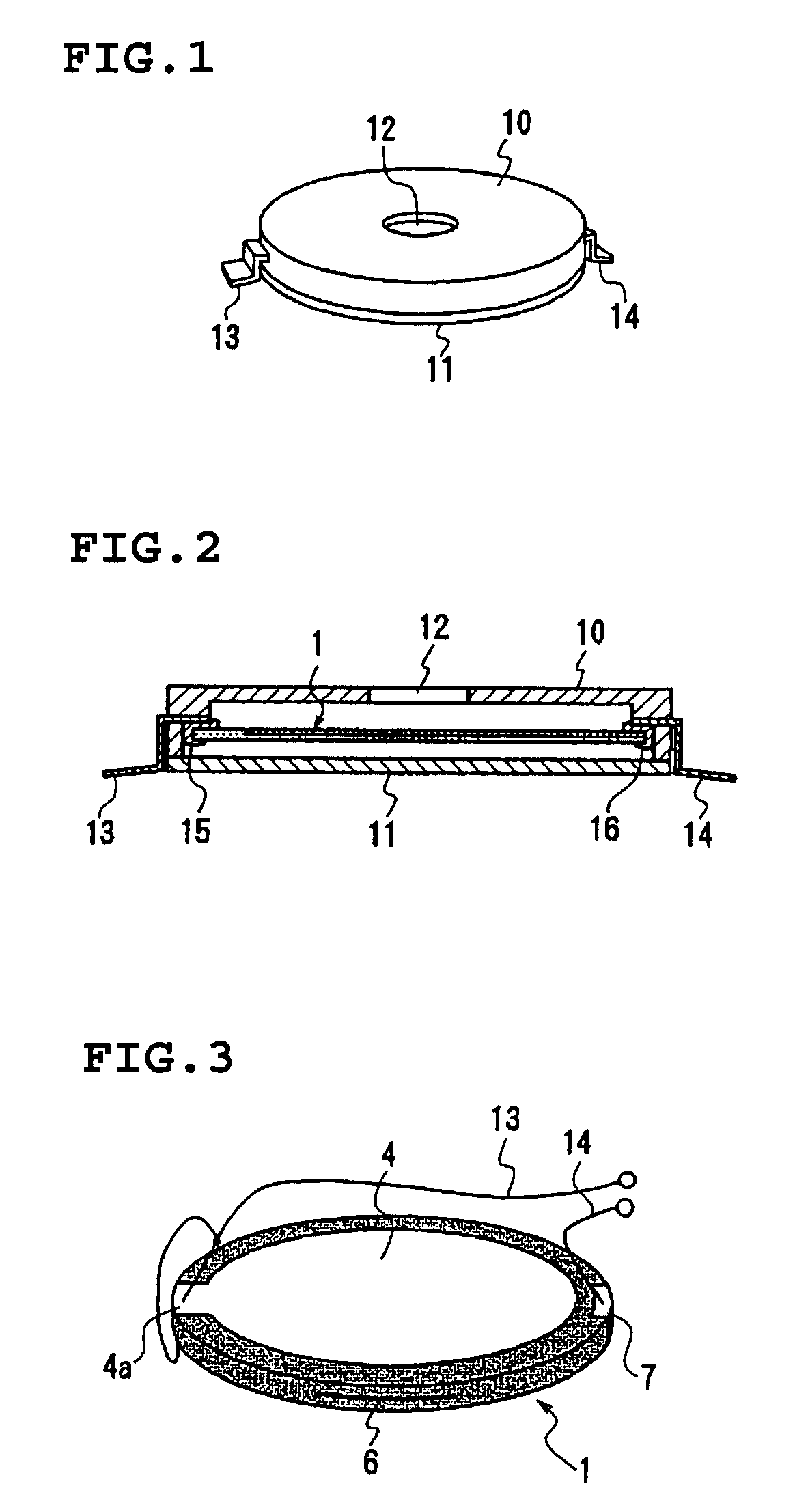
[0045]FIGS. 1 and 2 show a piezoelectric electroacoustic transducer in accordance with a first preferred embodiment of the present invention. This piezoelectric electroacoustic transducer preferably includes a disk-shaped diaphragm (laminated body) 1, a substantially circular case 10 accommodating the diaphragm 1, and a bottom cover 11. A sound discharging hole 12 is provided on the top surface of the case 10, and the bottom cover 11 is adhered to an opening of the bottom surface of the case 10. External connection terminals 13 and 14 are provided at symmetric positions on the outer periphery of the case, and are fixed by insert moldings or other suitable fixing devices. Part of each of the terminals 13 and 14 extends to the inside of the case 10. The electrode of the diaphragm 1 is electrically connected to the internally exposed portions of the terminals 13 and 14 by conductive adhesives 15 and 16, respectively. The gaps provided between the case 10 and the outer periphery of the ...


PUM


Abstract

A piezoelectric electroacoustic transducer eliminates the need for the interconnection between main surface electrodes and internal electrodes, and is capable of constructing a bimorph diaphragm using a simple connection structure. The piezoelectric electroacoustic transducer includes a laminated body formed by laminating two or three piezoelectric ceramic layers, main surface electrodes each provided on the top and bottom main surfaces, and an internal electrode provided between any adjacent two piezoelectric ceramic layers. In the piezoelectric electroacoustic transducer, all ceramic layers are polarized in the same direction with respect to the thickness direction, and by applying an alternating voltage across the main surface electrodes and the internal electrode, the laminated body generates a bending vibration in its entirety.

Description

[0001]This application is a Continuation of U.S. patent application Ser. No. 09 / 650,041 filed Aug. 29, 2000, now U.S. Pat. No. 6,741,710.BACKGROUND OF THE INVENTION[0002]1. Field of the Invention[0003]The present invention relates to a piezoelectric electroacoustic transducer such as a piezoelectric receiver, piezoelectric sounder, piezoelectric speaker, and piezoelectric buzzer, and more particularly, to a diaphragm of a piezoelectric electroacoustic transducer.[0004]2. Description of the Related Art[0005]A piezoelectric electroacoustic transducer has been widely used for a piezoelectric receiver, piezoelectric buzzer, or other suitable device. This piezoelectric electroacoustic transducer typically includes a unimorph type diaphragm which is constructed by adhering a circular metallic plate to one surface of a circular piezoelectric ceramic plate, wherein the outer peripheral portion of the diaphragm is supported in a circular case, and wherein an opening of the case is closed by ...

Claims


Application Information

Patent Timeline
IPC IPC(8): H04R17/00
CPCH04R1/06H04R17/00H04R31/003H04R2307/023
Inventor TAKESHIMA, TETSUOKISHIMOTO, TAKESHIYAMAMOTO, TAKASHIHAMADA, KAZUAKI
Owner MURATA MFG CO LTD
Learn More