Dual phased-locked loop structure having configurable intermediate frequency and reduced susceptibility to interference

Inactive Publication Date: 2005-11-29
SKYWORKS SOLUTIONS INC
View PDF6 Cites 20 Cited by
  • Summary
  • Abstract
  • Description
  • Claims
  • Application Information

AI Technical Summary

Benefits of technology

[0008]Interference from an asynchronous source will cause spurious tones in the phase noise spectrum of the VCO. As the interference modulates the instantaneous frequency, an interferer at a close frequency (i.e., small Δf) will produce a larger phase noise component. Interference from a synchronous source can have several effects: first, if the interference is additive, it may transfer its phase noise to the VCO and thus reduce the jitter removal capabilities of the system. Second, if the interference is subtractive, it may reduce the intended bandwidth of the clock ‘cleaning’ system and thus add additional oscillator phase noise into the system. Third, if the interference is subtractive and strong relative to the gain within the PLL, it will destabilize the operating point and add phase error due to oscillations.
[0009]A wider bandwidth PLL (i.e., one with more gain in the loop) is more robust to interference effects for the following reasons: (1) asynchronous interferers at offset frequencies closer than the bandwidth are suppressed by the loop (these would be the worst phase noise offenders); and (2) stronger synchronous interferers will have a noticeable effect on the phase noise only if the gain from the interferer gets to be in the same order of magnitude as the gain in the PLL, thus an increase in bandwidth by 10× will decrease the sensitivity to interference by 10×.
[0010]To improve performance in the face of such interference, and in a broader context, to reduce the problem of synchronous interference into a low bandwidth loop, the PLL function may be implemented as a dual-loop structure having a first PLL circuit (i.e., a first loop) which generates an intermediate signal from the reference signal, and a second PLL circuit (i.e., a second loop) which g

Problems solved by technology

In an exemplary system containing a PLL circuit configured for clock/data recovery of an incoming data signal, the recovered clock signal may suffer interference from a substantially identical frequency signal in a nearby transmit sub-system for an outgoing data signal having the same data rate.
Such interference may alternatively be caused by another PLL circuit within a second receive channel.
In some cases, the interference signal may operate at a much lower (i.e., very different) frequency, but its harmonics may be substantially the same frequency as the PLL operating frequency and may cause spurious phase noise of the PLL output signal.
Interfe

Method used


Image

  • Dual phased-locked loop structure having configurable intermediate frequency and reduced susceptibility to interference
  • Dual phased-locked loop structure having configurable intermediate frequency and reduced susceptibility to interference
  • Dual phased-locked loop structure having configurable intermediate frequency and reduced susceptibility to interference

Examples


Example

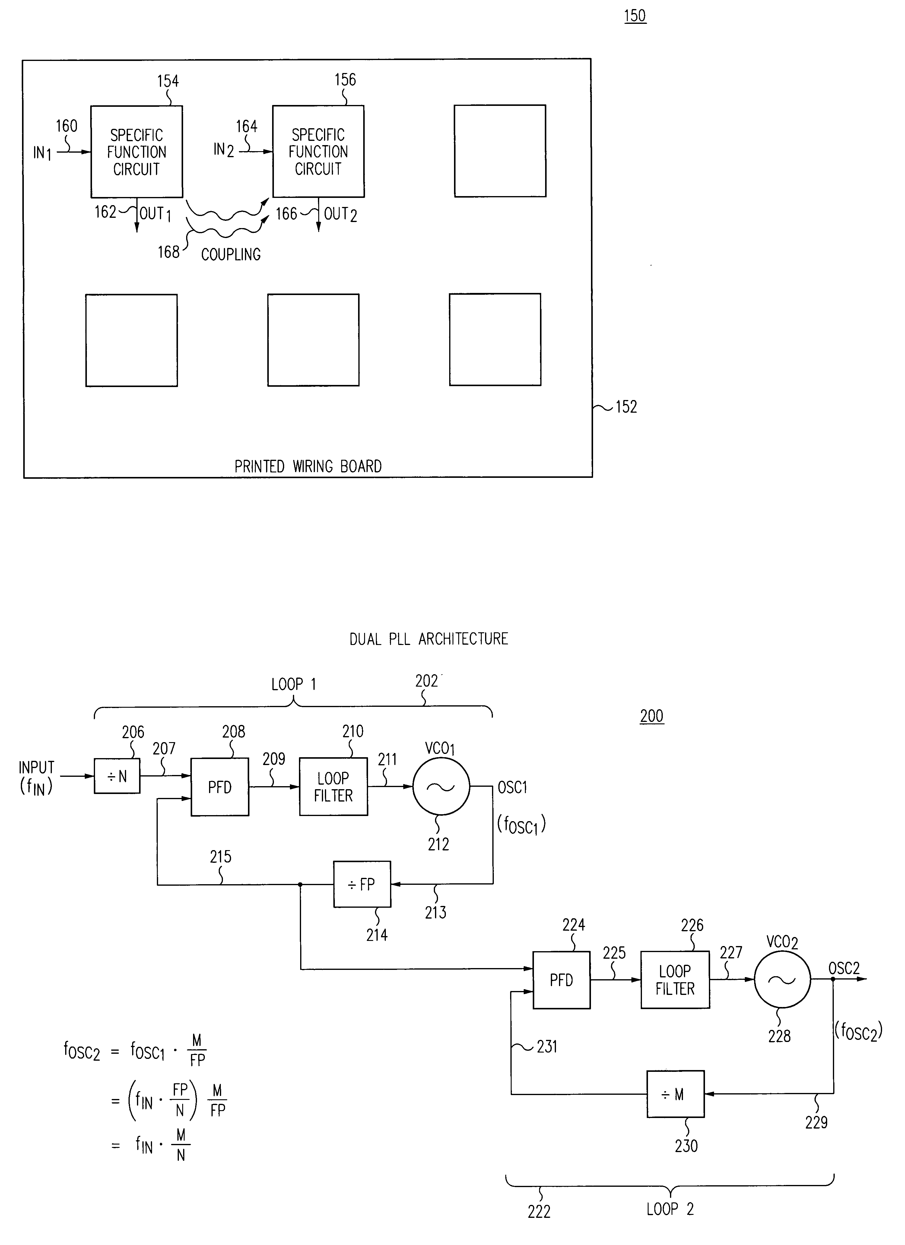
[0023]Referring now to FIG. 3, a printed wiring board 152 is shown containing several functional circuit blocks. Each of two such circuit blocks 154 and 156 are depicted as providing a specific function, here represented as a function responsive to a respective input signal IN1, IN2, and generating a corresponding output signal OUT1, OUT2. As shown, the Specific Function circuit block 154 receives an IN1 signal conveyed on node 160 and generates a corresponding output signal OUT1 conveyed on node 162 in accordance with the Specific Function. Similarly, the Specific Function circuit block 156 receives an IN2 signal conveyed on node 164 and generates a corresponding output signal OUT2 conveyed on node 166 in accordance with the Specific Function.

[0024]If these two circuit blocks 154, 156 are placed in close proximity to each other, one or more of the signals related to one of the circuit blocks may couple to the other circuit block, as indicated by coupling 168 from circuit block 154 ...


PUM


Abstract

A PLL function may be implemented as a dual-loop structure having a first PLL circuit which generates an intermediate signal from the reference signal, and a second PLL circuit which generates an output signal from the intermediate signal. The intermediate signal frequency is preferably chosen at a value in which potential interference signals do not have much energy. The first loop preferably has low bandwidth to provide good input jitter attenuation, while second loop preferably has higher bandwidth to reduce phase noise of the output signal. The circuit preferably provides for a choice of several different intermediate frequencies to allow use where different intermediate frequencies may exist in each system. Moreover, in a system having two such dual-loop PLL circuits, each can be configured with a different intermediate frequency, so that interference from one to the other is reduced.

Description

BACKGROUND[0001]The present invention relates to phase-locked loop systems, and particularly those incorporating more than one phase-locked loop circuit.[0002]Phase locked loop (PLL) circuits are well-known in the art. Initially they were very expensive to implement, and found use in only the most technically-demanding and / or cost-insensitive applications. However, as the cost of integrated circuit technology has decreased over the years, and as the performance capability of such integrated circuit technology has increased, PLLs are currently extremely inexpensive to implement and are found in wide use in many applications.[0003]FIG. 1 is a block diagram of a traditional phase locked loop circuit 100 configured to generate an output signal having a frequency which is a multiple M / N of an input signal frequency. The PLL circuit 100 includes a phase detector 101, a loop filter 102, and a voltage controlled oscillator (VCO) 104. An input signal is conveyed on node 112 to a first divide...

Claims


Application Information

Patent Timeline
IPC IPC(8): G06F1/04G06F7/68H03L7/183H03L7/23
CPCG06F7/68H03L7/183H03L7/23
Inventor HUANG, YUNTENGZHANG, LIGANGTHOMSEN, AXEL
Owner SKYWORKS SOLUTIONS INC
Why Eureka
Try Eureka