Micro-lens sheet and projection screen

a technology of projection screen and micro-lens, which is applied in the field of micro-lens sheet, can solve the problems of reduced transmission light, difficult selection, and difficulty in controlling the light diffusing characteristics in only vertical directions, and achieves the effects of reducing optical absorption, reducing optical absorption, and forming a fine bm

Inactive Publication Date: 2005-11-29
TOPPAN PRINTING CO LTD
View PDF14 Cites 23 Cited by
  • Summary
  • Abstract
  • Description
  • Claims
  • Application Information

AI Technical Summary

Benefits of technology

[0036]Yet another object of the present invention is to provide a micro-lens sheet which can control an emission direction of the display light emitted from the lens section in a wider perspective range (scope) by disposing the unit lens groups in fine pitch such as 200 μm or finer in a micro-lens sheet which is preferable for a lens sheet to be used for a transmission projection screen containing two pieces of lens sheet in combination particularly with a Fresnel lens sheet.
[0037]Yet another object of the present invention is to provide a micro-lens sheet which can easily form a fine BM in which a borderline between an aperture section and the shading section is clear when a BM having a high shading ratio (75%) is formed on a micro-lens sheet away from the lens section.
[0038]Yet another object of the present invention is to provide a projection screen using a micro-lens having sufficient optical characteristics for a screen with less optical absorption, less gain reduction, and controlled white scattering easily with large area.
[0039]Yet another object of the present invention is to provide a projection screen using a micro-lens of which material cost and manufacturing cost are inexpensive.

Problems solved by technology

It is difficult to select combination such as refractive indexes between the light diffusing particle and the resin, diameter of the light diffusing particle (and its distribution), and diffusion characteristics.
It is also difficult to control the light diffusing characteristics in only vertical direction from a structural point of view.
Therefore, reduction in the transmitted light (decrease in displaying brightness) is caused; thus, product cost increases.
However in addition to a lens sheet for controlling the light diffusing characteristics in a horizontal direction, adding a lens sheet for controlling the light diffusing characteristics in a vertical direction may cause a difficulty in aligning both lenses for setting the screen.
Also, such factors may cause increase in the product cost because structural member increase.
Therefore, in a case in which the shading pattern is formed by the self alignment method, the position where the characteristics of the photosensitive resin layer changes cannot be determined precisely.
In particular, in a case in which the shading ratio is enhanced so as to realize an image with higher contrast, there is a problem in that it is difficult to form a BM having a clear borderline between a fine aperture section and the shading section when parallel disposition pitch between the unit lens is very fine and each one of the unit lens is fine.
In the micro-lens array, wider perspective angle is necessary; therefore, there are disadvantages such as deteriorated quality in the image due to absorption of light by the diffusion layer and white scattering, and reduced screen gain caused by wide diffusion.
Thus, there is a problem in that cost for parts and manufacturing process become expensive.
Thus, it is not possible to control the perspective angle by independently changing the shape of one of the lenticular lenses.
Therefore, there is a limit for controlling range for the perspective angle; thus, such a limit is not preferable from practical point of view.
However, it is difficult to compatibly realize such depth in lens thug and picture size because of the depth to be molded.
Because of this, even if necessary optical performance can be realized as long as an image area is small, due to a problem in manufacturing process, it is difficult to enlarge the image area.

Method used


Image

  • Micro-lens sheet and projection screen
  • Micro-lens sheet and projection screen
  • Micro-lens sheet and projection screen

Examples


first embodiment

[0083]FIG. 12 is a cross section showing a general structure of a liquid crystal rear projection television. Reference numeral 31 is a light source lamp. Reference numeral 32 indicates an optical structural section. Reference numeral 33 indicates a liquid crystal panel. Reference numeral 34 indicates a first mirror. Reference numeral 35 indicates a projecting lens. Reference numeral 36 indicates a second mirror. Reference numeral 37 indicates a screen. FIG. 13 is a cross section viewed in A-A section in the screen 37. In FIG. 13, Reference numeral 38 indicates a Fresnel lens. Reference numeral 39 indicates a micro-lens. Reference numeral 40 indicates a black matrix section. Reference numeral 41 is a protection layer. Reference numeral 42 indicates a hard-coat section.

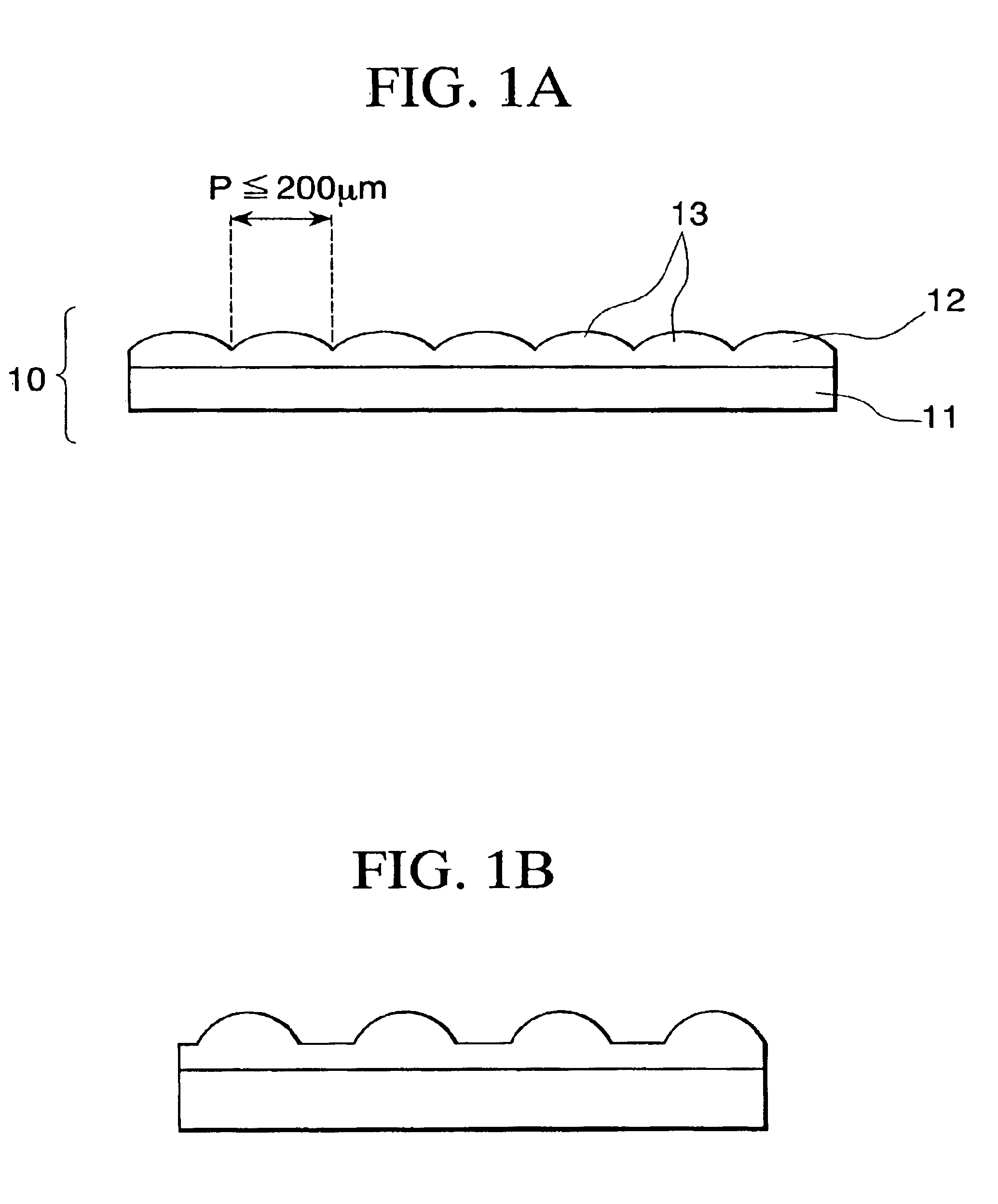
[0084]FIGS. 1A and 1b are cross sections showing a micro-lens sheet 10.

[0085]On one surface of a base board 11, the micro-lens array section 12 made from a reacted product of radioactive-ray-curable-resin is bonded. In ...

second embodiment

[0101]FIG. 5 is a cross section showing an example for a micro-lens sheet 101 according to the present invention.

[0102]On one surface of a transparent supporting member 103, a lens section (unit lens group) 102 is formed by using a reacted product of radioactive-ray-curable-resin. A shading patter (BM) 105 having an aperture in a spot manner is formed in a position corresponding to a non-light-condinsing section by each of the unit lens on a flat surface which is opposite to the transparent supporting member 103 via a positive photosensitive adhesive layer 104.

[0103]For a transparent supporting member 103, polyethylene terephthalate (PET) or polycarbonate (PC) can be named.

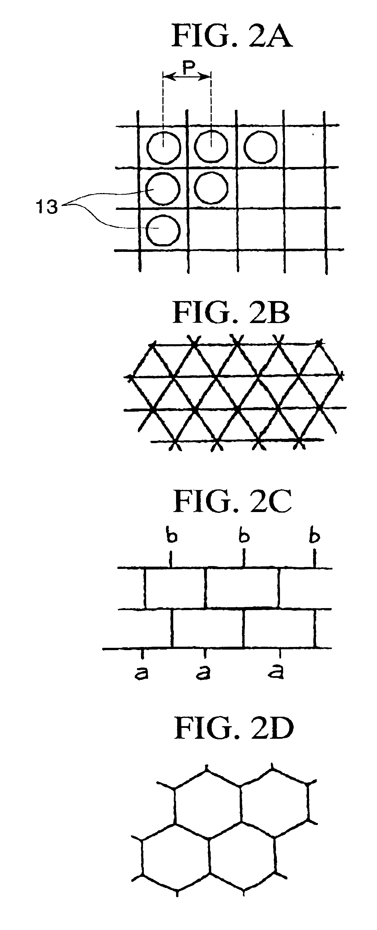
[0104]It is preferable that the diameter of the unit lens and its disposition pitch are 200 μm or less so as to obtain a screen which is suitable for observing the fine resolution image.

[0105]Such a fine pitch operation can be obtained by performing a molding operation for forming a lens according to 2P method (ph...

third embodiment

[0121]Embodiments of a projection screen as an example for the present invention is explained as follows with reference to the drawings.

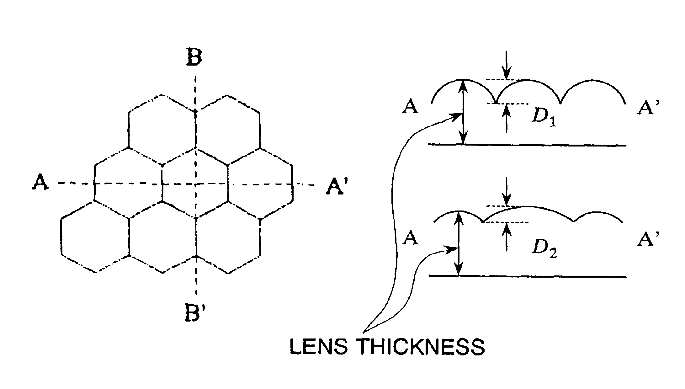
[0122]FIGS. 8A and 8B are general views for an element lens of a micro-lens sheet used in a projection screen according to the present invention.

[0123]FIG. 9 is a perspective view of an element lens contained in the micro-lens array sheet used in the projection screen according to the present invention.

[0124]FIG. 10 is a cross section of an element lens in a vertical direction contained in the micro-lens array sheet used in the projection screen according to the present invention.

[0125]FIG. 11 is a cross section of an element lens in a horizontal direction contained in the micro-lens array sheet used in the projection screen according to the present invention.

[0126]Here, regarding the lens array sheet shown in this embodiment, the shape of the lens are actually designed, and these drawings are made according to these designed lens shape.

[0127]In FIG...


PUM


Abstract

In order to provide a micro-lens sheet in which unit lenses are disposed in highly accurate pitch so as to control the light diffusing characteristics of the light emission direction not only in a horizontal direction but also over 360 degrees by using the lens function of one piece of lens sheet, a micro-lens sheet has a micro-lens array section in which unit lenses are disposed in approximate matrix in a second dimensional manner on at least one surface of a base board, and the micro-lens array section is formed on only one surface of the base board, the micro-lens array section includes the unit lens having an aspherical shape, and disposition pitch of neighboring unit lenses is 200 μm or shorter.

Description

TECHNICAL FIELD[0001]The present invention relates to a micro-lens sheet. The present invention particularly relates to a micro-lens sheet which is preferable to be used for an image displaying screen (transmission projection screen or a rear-projection screen) for a rear-projection television apparatus.[0002]Also, the present invention relates to a projection screen using a lens array sheet which is used for a rear-projection display (television / display) such as a liquid-crystal projection television / display.BACKGOURND ART[0003]Commonly, in a transmission projection screen, a Fresnel lens sheet and a lenticular sheet are assembled.[0004]A Fresnel lens sheet emits a light (which disperses from a small-diameter lens) which is projected from a projector to a lenticular sheet as an approximate parallel light by using a converging lens.[0005]The lenticular sheet widens horizontally a range of the projected light which is incident as an approximate parallel light by the Fresnel lens shee...

Claims


Application Information

Patent Timeline
Patent Type & Authority Patents(United States)
IPC IPC(8): G03B21/62
CPCG03B21/625H04N5/72
Inventor EBINA, KAZUYOSHIABE, TAKASHIMIYASHITA, MASARUTAKAHASHI, SUSUMU
Owner TOPPAN PRINTING CO LTD
Why Eureka
Try Eureka