Data alignment compensator

a data alignment and compensator technology, applied in the field of communication networks, can solve the problems of low serial link speed, low data volume, and sensitive issues of pin counts and cost, and achieve the effects of high volume data path, high speed, and fast ra

Inactive Publication Date: 2005-11-29
IBM CORP
View PDF26 Cites 20 Cited by
  • Summary
  • Abstract
  • Description
  • Claims
  • Application Information

AI Technical Summary

Benefits of technology

[0023]By simultaneously transmitting groups of bit streams serially over different transmission media, a high speed, high volume data path is provided. The data path uses fewer pins and transfers data at a faster rate than a traditional bus structure.

Problems solved by technology

Even though bus structure transfers data relatively fast, it is expensive and requires multiple pins (one for each bit) at the interface.
There are many designs in which pin counts and cost are very sensitive issues.
As a consequence, bus structures are not suitable for interconnecting sub-assemblies.
Probably, the most severe of all the shortcomings is that the serial links are relatively low speed.
Surely, this speed makes them unsuitable for use in high speed, say 500 and greater Mbps, applications.
Even though these systems point in the right direction, they suffer several defects including unnecessary use of pins to transmit clock signal, etc.

Method used


Image

  • Data alignment compensator
  • Data alignment compensator
  • Data alignment compensator

Examples


Embodiment Construction

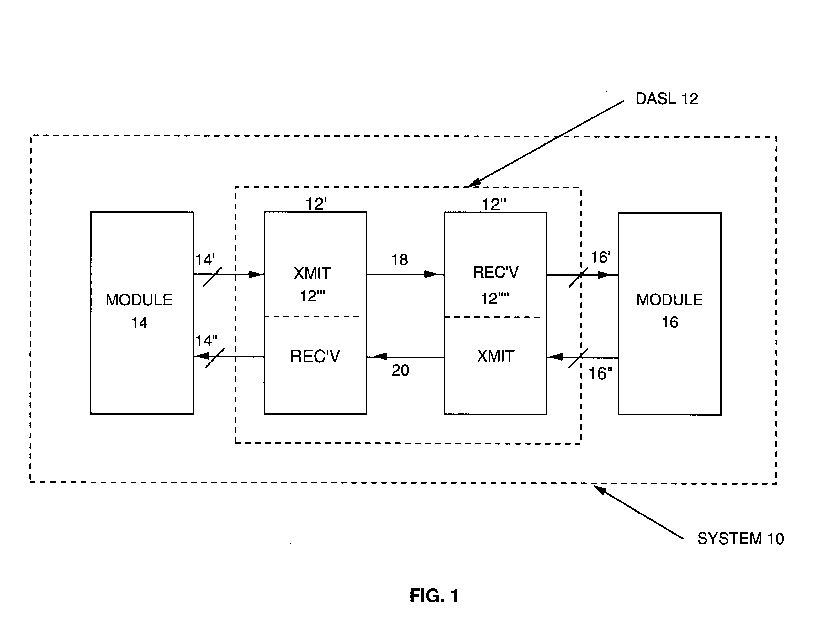
[0047]FIG. 1 shows a block diagram of the System 10 embodying the teachings of the present invention. The System 10 includes Module 14 and Module 16 interconnected by the Data Align Serial Link (DASL) Interface 12. The System 10 could be a subsystem of the larger system fabricated on a motherboard. The DASL Interface 12 provides high speed communication between Module 14 and Module 16. The modules may be CMOS ASIC or any other of the well known process related Large Scale Integration (LSI) chip. Each of the modules is connected by input and output bus respectively to the DASL Interface 12. The angled line crossing a horizontal line indicates a bus structure throughout the figures of this document.

[0048]The DASL Interface 12 includes two identical sections labelled 12′ and 12″, respectively. Each of the sections is connected by busses to one of the modules. To this end, Section 12′ is connected by Bus 14′ and 14″, respectively. The direction of signal flow in Bus 14′ and Bus 14″ is i...


PUM


Abstract

An apparatus and method that correct skew associated with data receive from different transmission links. A known training pattern is sent through the transmission links. The training pattern is recovered and forwarded through delay registers / selecter logic to a memory buffer. A programmed controller accesses the memory and searches for the training pattern. If the training pattern is found for each transmission link, the offsets between the transmission links are determined and are used by the delay registers / selecter logic to adjust the position of the pattern so that the patterns from each link is linearly aligned within the memory buffer.

Description

CROSS-REFERENCE TO RELATED PATENT APPLICATIONS[0001]This application claims the benefit of U.S. Provisional Application Ser. No. 60 / 089,240, filed Jun. 15, 1998.[0002]The listed related patent applications are incorporated herein by reference:[0003]patent application Ser. No. 09 / 330,968, filed Jun. 11, 1999, entitled: High Speed Parallel / Serial Link for Data Communication;[0004]patent application Ser. No. 09 / 330,735, filed Jun. 11, 1999, entitled: System that Compensates for Variances Due to Process and Temperature Changes;[0005]patent application Ser. No. 09 / 330,713, filed Jun. 11, 1999, entitled: Initialization System for Recovering Bits and Group of Bits from a Communications Channel;[0006]patent application Ser. No. 09 / 330,971, filed Jun. 11, 1999, entitled: Low Differential Driver.BACKGROUND OF THE INVENTION[0007]1. Field of the Invention[0008]The present invention relates to communications network in general and, in particular, to systems for interconnecting electrical sub-sys...

Claims


Application Information

Patent Timeline
Patent Type & Authority Patents(United States)
IPC IPC(8): H04B7/005H04L1/20H04L12/26
CPCH04L1/205
Inventor BUCHANAN, BRIANMARSHALL, JOHNRIEDLE, CHRISTOPHER G.
Owner IBM CORP
Why Eureka
Try Eureka