Evaporative burner

a technology of evaporative burner and burner body, which is applied in the direction of combustion types, machines/engines, lighting and heating apparatus, etc., can solve the problems of existing designs that do not address the needs of compact and high efficiency, and the burner power is limited to 12 kwt, so as to achieve the burner power in a relatively short time, the effect of improving the evaporation burner

Inactive Publication Date: 2005-12-06
NEW POWER CONCEPTS
View PDF27 Cites 19 Cited by
  • Summary
  • Abstract
  • Description
  • Claims
  • Application Information

AI Technical Summary

Benefits of technology

[0008]Accordingly, an improved evaporation burner is provided. Certain embodiments of this evaporative burner are capable of igniting over a wide temperature range and reaching full burner power in a relatively short time. Furthermore, other embodiments of the evaporative burner, due to the gradual evaporation of fuel, provide heat uniformly to the heater head surfaces in the combustion chamber.
[0014]Other embodiments of the burner include a recuperative heat exchanger such as a preheater. The preheater may heat the air entering the evaporation chamber. The heated air may mix with the evaporated fuel to form the optimal fuel-air mixture to sustain a flame.

Problems solved by technology

The relatively low burner power level required in a <3 kWe (kilowatt electric) Stirling engine provides an additional challenge to burner design.
However, such an approach is limited to burner powers above 12 kWt (kilowatt thermal) and thus engines above 3 kWe.
Existing designs do not address the needs of a compact, high efficiency and low emissions of external combustion engine such as Stirling cycle engine and the capability to preheat the air without detrimental effects.

Method used


Image

  • Evaporative burner
  • Evaporative burner
  • Evaporative burner

Examples


Embodiment Construction

[0024]Definitions. As used in this description and the accompanying claims, the following terms shall have the meanings indicated, unless the context otherwise requires:[0025]FAE: Fuel-Air Equivalence (FAE) ratio=Actual Fuel-Air Mass Ratio / Stoichiometric Fuel-Air Mass Ratio.

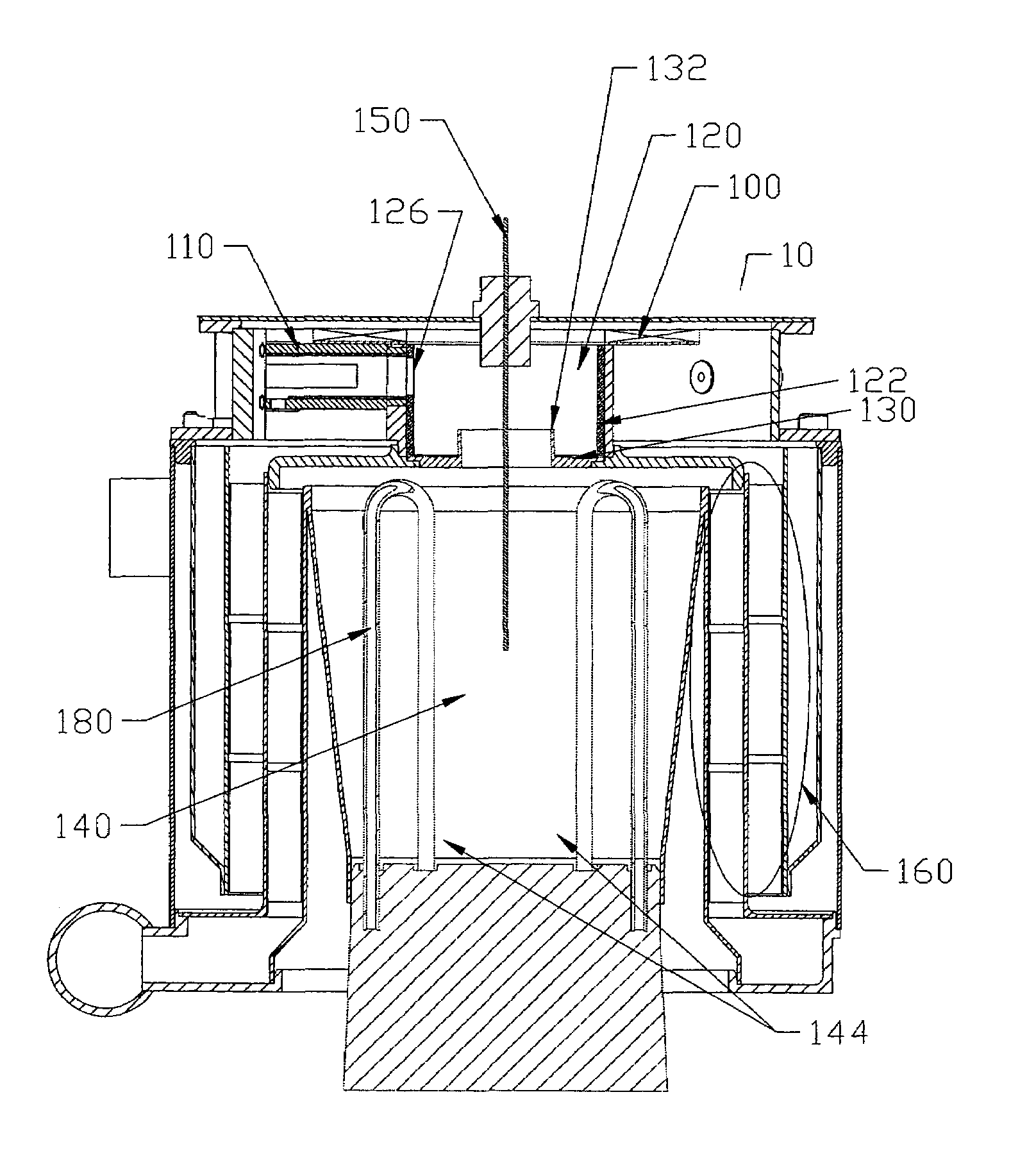
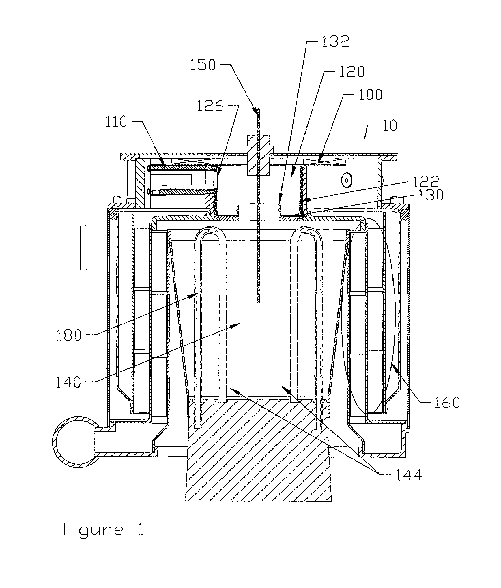
[0026]FIG. 1 illustrates an embodiment of the invention in the exemplary application for providing heat uniformly to the walls of a combustion chamber. While embodiments of the invention will be described generally with reference to an external combustion engine such as a Stirling cycle engine, it is to be understood that many engines, burners, and other machines may similarly benefit from various embodiments and improvements that are subjects of the present invention. It also understood that liquid fuel includes pumpable hydrocarbon liquids including, but not limited to diesel, gasoline, heating oil, alcohols, and military fuels such as JP8.

[0027]The evaporative burner of the present invention may be used in Sti...


PUM


Abstract

An evaporative burner that includes an igniter assembly, a swirler, an evaporation chamber, and a reverse throat. The reverse throat has raised ends that protrude into the evaporation chamber. The reverse throat in combination with the evaporation chamber and the swirler, facilitate the recirculation of air in the evaporation chamber such that a flame is stabilized near the evaporation chamber walls. This flame gradually evaporates the fuel in the lining of the evaporation chamber. The fuel-air mixture results in a steady and uniformly distributed flame in the combustion chamber. This flame can heat uniformly the walls of the combustion chamber, and thus be applicable for high efficiency and low emissions applications. Furthermore, this burner can start and reach full burner power rapidly.

Description

CROSS REFERENCE TO RELATED APPLICATIONS[0001]The present application is a U.S. continuation-in-part patent application of U.S. patent application Ser. No. 10 / 382,089, filed on Mar. 05, 2003 now U.S. Pat. No. 6,708,481, entitled “FUEL INJECTOR FOR A LIQUID FUEL BURNER,” which is incorporated herein by reference in its entirety, which claims priority from U.S. provisional patent application, Ser. No. 60 / 365,657, filed Mar. 19, 2002, entitled “FUEL INJECTOR FOR A LIQUID FUEL BURNER,” which is incorporated herein by reference in its entirety.TECHNICAL FIELD AND BACKGROUND ART[0002]External combustion machines, for example Stirling cycle machines, including engines and refrigerators, have a long technical heritage. Walker, Stirling Engines, Oxford University Press (1980), describing Stirling cycle engines in detail, is incorporated herein by reference. The principle underlying the Stirling cycle engine is the mechanical realization of the Stirling thermodynamic cycle: isovolumetric heati...

Claims


Application Information

Patent Timeline
Patent Type & Authority Patents(United States)
IPC IPC(8): F23D11/26F23D11/40F23D99/00F23K5/04F23N1/00
CPCF23D11/26F23D11/402F23D99/006F23K5/04F23N1/005F23K2900/05001F23K2900/05003F23D91/04
Inventor LANGENFELD, CHRISTOPHER C.LAROCQUE, RYAN KEITHMACEACHERN, ANGUS A.NORRIS, MICHAEL G.
Owner NEW POWER CONCEPTS
Why Eureka
Try Eureka