Miter saw with laterally tiltable circular saw blade

a circular saw blade, laterally tiltable technology, applied in the field of miter saws, can solve the problems of disadvantageous greater outer diameter of bevel gear, bulky case, and reduced axial thickness of abutment portion, so as to reduce the length of the lower wall, reduce the length, and reduce the length

Inactive Publication Date: 2005-12-06
HITACHI KOKI CO LTD
View PDF13 Cites 20 Cited by
  • Summary
  • Abstract
  • Description
  • Claims
  • Application Information

AI Technical Summary

Benefits of technology

[0018]Because not the second intermediate shaft bearing but the pinion is positioned closest to the circular saw blade among the components on the intermediate shaft, the axial thickness of the abutment portion can be as small as possible as long as the abutment portion can sustain abutment against the gear when the gear is force fitted into the intermediate shaft. As a result, the axial thickness of the abutment portion can be reduced. Consequently, the gear can also be positioned close to the circular saw blade, which can reduce a length of a lower wall, the length being in parallel with the axial direction of the intermediate shaft. The reduction of the length can increase an effective cutting length between the upper surface of the base and the slanting wall, thereby enabling cutting to a thicker workpiece.

Problems solved by technology

Therefore, an outer diameter of the bevel gear must disadvantageously be greater than an outer diameter of an ordinary spur gear in an attempt to provide a power transmission force by way of the bevel gear equal to a power transmission force by way of the spur gear, because a center area of the teeth of the bevel gear in its axial direction is considered to provide a mean or average level of a strength.
Consequently, resultant case becomes bulky.
This becomes impossible to perform a slant cutting to a thick workpiece.
Then, a case for accommodating the power transmission mechanism must become bulky.

Method used


Image

  • Miter saw with laterally tiltable circular saw blade
  • Miter saw with laterally tiltable circular saw blade
  • Miter saw with laterally tiltable circular saw blade

Examples


Embodiment Construction

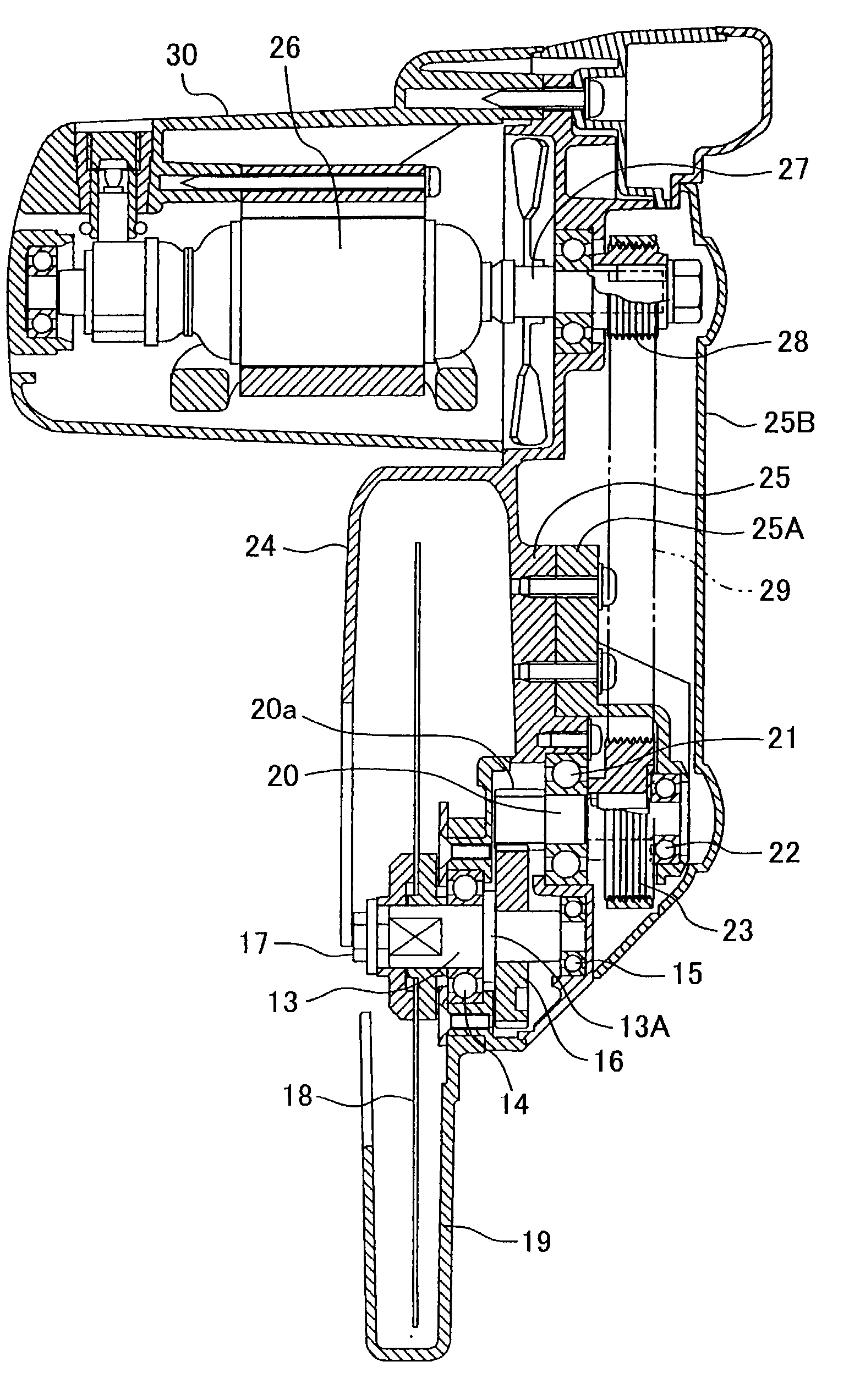
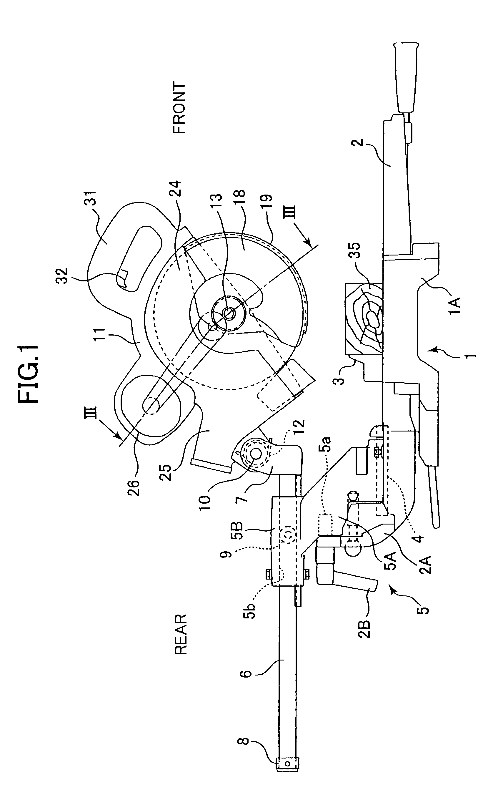
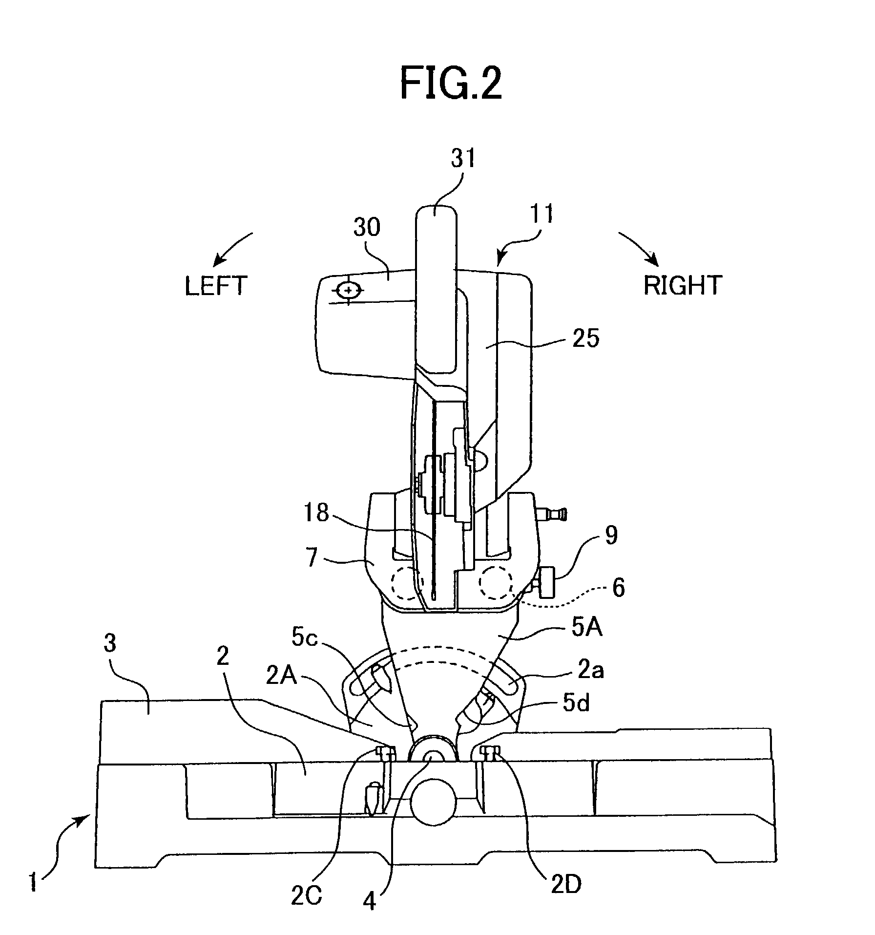
[0025]A miter saw having a mechanism for laterally tilting a circular saw blade according to one embodiment of the present invention will be described with reference to FIGS. 1 through 4. As shown in FIGS. 1 and 2, the miter saw generally includes a base portion 1 on which a workpiece 35 is mounted, a main body portion 11 adapted for cutting the workpiece 35, and a support portion 5 for movably supporting the main body portion 11 with respect to the base 1 in a vertical direction, in a frontward / rearward direction, and in a lateral direction, i.e., in rightward / leftward direction (FIG. 2).

[0026]The base portion 1 includes a base 1A and a turntable 2 rotatable on the base 1A in a horizontal plane. An upper surface of the turntable 2 is flush with an upper surface of the base 1A. The workpiece 35 such as a wood is mounted on the base 1A and the turntable 2. A fence 3 protrudes from the upper surface of the base 1A for positioning the workpiece 35 by abutting a vertical surface of the ...


PUM

PropertyMeasurementUnit
angleaaaaaaaaaa
radiusaaaaaaaaaa
thicknessaaaaaaaaaa

Abstract

A miter saw including a base portion and a main body portion laterally tiltable and vertically pivotable. The main body portion includes a circular saw blade whose one side is provided with a power transmission mechanism. The mechanism includes a motor shaft pulley fixed to a motor shaft of a motor, a saw blade shaft extending in parallel with the motor shaft and an intermediate shaft extending in parallel with the saw blade shaft and positioned between the motor shaft and the saw blade shaft. On the saw blade shaft, a first saw blade shaft bearing, a flanged abutment portion, a gear and a second saw blade shaft bearing are arrayed in an order from the circular saw blade. On the intermediate shaft, a pinion meshedly engaged with the gear, a first intermediate shaft bearing in alignment with the second saw blade shaft bearing, an intermediate shaft pulley in alignment with the motor shaft pulley and a second intermediate shaft bearing are arrayed in this order from the circular saw blade. The gear and the pinion are positioned closest to the circular saw blade, which permits an axial thickness of the abutment portion to be reduced for reducing entire axial thickness of the power transmission mechanism.

Description

BACKGROUND OF THE INVENTION[0001]The present invention relates to a miter saw having a base and a circular saw blade vertically movable and laterally tiltable with respect to an upper surface of the base supporting a workpiece to be cut.[0002]Japanese Patent Publication No.2630537 discloses such type of a miter saw with a simplified power transmission mechanism for transmitting a rotation of a motor shaft to a saw blade shaft. To this effect, a motor housing and a motor are provided at one side of the circular saw blade, and the motor shaft and the saw blade shafts extend to intersect with each other. The motor shaft is tapered such that a diameter of the motor shaft is gradually reduced toward the saw blade shaft, and further, a gear portion is formed at an outer surface of the motor shaft. On the other hand, the saw blade shaft is coaxially fixed with a bevel gear meshedly engageable with the gear portion of the motor shaft. A diameter of the bevel gear is gradually increased towa...

Claims


Application Information

Patent Timeline
Patent Type & Authority Patents(United States)
IPC IPC(8): B23D45/02B23D45/04B23D45/14B23D47/12B27B9/00B27B9/02
CPCB23D45/048B23D47/12Y10T83/7697Y10T83/8773
Inventor USHIWATA, SHIGEHARUTERASHIMA, HIDEAKI
Owner HITACHI KOKI CO LTD
Why Eureka
Try Eureka